Section 5 Operating Instructions
S7M / S8M Manual
www.rottlermfg.com
5-4
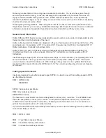
Following is a description of the cutting inserts available from Rottler. The inserts have gone through
extensive performance testing. To take full advantage of the capabilities of your Rottler machine, we
highly recommend Rottler cutting tools be used. Rottler machine performance can be significantly
reduced if qualified tooling is not used. Using an incorrect insert can result in surface finish inconsistency,
short tool life, and poor surface finish.
Following are general guidelines. When using these inserts it is best to refer to the operator manual of
the particular machine you are using. Rottler Manufacturings latest operator manuals have more detailed
information on feeds and speeds for the particular machine and cutterhead that you are using.
General Insert Information
Rottler CBN and PCD Inserts are laser marked with our part number on one side. On single sided inserts,
the part number is on the back side of the insert.
Rottler surfacing insert toolholders are designed so they can hold square and round inserts that are of the
same basic size. For example, a 3/8” IC round and 3/8” IC square insert will fit into the standard 3/8” IC
Rottler toolholders. IC stands for inscribed circle.
Rottler S, F60, F70 and F100 Series surfacing cutterheads are supplied standard with Rottler 3/8”
IC toolholders fitted to our surfacing heads. Optional 1/2” toolholders are interchangeable with 3/8”
toolholders.
Insert breaking or chipping can be caused by several things. It can be caused by not operating the insert
at the correct RPM. It is very typical for an insert to break or chip when cutting too slow. Interrupted
cuts can cause an insert to break as well. When making a heavy sleeve cut in a cylinder that has been
cracked it is often required to slow the RPM down to 1/2 the normal operating speed to prevent chipping
of the insert.
Cutting Speed Calculation
Inserts are designed to cut within a speed range (SFPM). In order to convert from cutting speed to RPM,
use the following formula:
RPM = SFPM X 3.82
DIAMETER
SFPM = Surface Feet per Minute
RPM = Revolutions per Minute
DIAMETER in Inches
The feed rate on most Rottler machines is designated in inches (mm) / revolution. The S7M/S8M have
feed rates designated in inches (mm) / minute. It is important to adjust the inches (mm) / minute rate
to obtain the correct load (inches / revolution). Following are the formulas to use. You do not have to
perform this calculation with an “A” model machine
If you know the RPM and the Feed Rate per Revolution you want, use the following formula to obtain the
correct Feed Rate per minute.
FRM = RPM X FRR
FRM = Feed Rate Inches per Minute
FRR = Feed Rate Inches per Revolution
RPM = Spindle Revolutions per Minute
Summary of Contents for S7M
Page 2: ......
Page 4: ......
Page 8: ...Section 1 Introduction S7M S8M Manual www rottlermfg com 1 4 ...
Page 17: ...Section 2 Installation S7M S8M Manual www rottlermfg com 2 8 ...
Page 18: ...Section 2 Installation S7M S8M Manual www rottlermfg com 2 9 ...
Page 38: ...Section 5 Operating Instructions S7M S8M Manual www rottlermfg com 5 9 ...
Page 57: ...Section 6 Maintenance S7M S8M Manual www rottlermfg com 6 17 Pneumatic Control Diagram ...
Page 66: ...Section 6 Maintenance S7M S8M Manual www rottlermfg com 6 26 ...
Page 68: ...Section 7 Troubleshooting S7M S8M Manual www rottlermfg com 7 2 ...
Page 71: ...Section 8 Machine Parts S7M S8M Manual www rottlermfg com 8 2 Pneumatic Assembly ...
Page 72: ...Section 8 Machine Parts S7M S8M Manual www rottlermfg com 8 3 Electrical Enclosure ...
Page 74: ...Section 8 Machine Parts S7M S8M Manual www rottlermfg com 8 5 Upper Housing ...
Page 76: ...Section 8 Machine Parts S7M S8M Manual www rottlermfg com 8 7 Spindle Base Front Section ...
Page 77: ...Section 8 Machine Parts S7M S8M Manual www rottlermfg com 8 8 Inner Outer Spindle Assembly ...
Page 78: ...Section 8 Machine Parts S7M S8M Manual www rottlermfg com 8 9 Spindle Base Bushings ...
Page 79: ...Section 8 Machine Parts S7M S8M Manual www rottlermfg com 8 10 Spindle Base Assembly ...
Page 80: ...Section 8 Machine Parts S7M S8M Manual www rottlermfg com 8 11 Left Ballscrew Support ...
Page 81: ...Section 8 Machine Parts S7M S8M Manual www rottlermfg com 8 12 Right Ballscrew Support ...
Page 82: ...Section 8 Machine Parts S7M S8M Manual www rottlermfg com 8 13 Home and Limit Switches ...
Page 83: ...Section 8 Machine Parts S7M S8M Manual www rottlermfg com 8 14 Pendant Assembly ...
Page 84: ...Section 8 Machine Parts S7M S8M Manual www rottlermfg com 8 15 Spindle Base ...
Page 85: ...Section 8 Machine Parts S7M S8M Manual www rottlermfg com 8 16 Chip Shield 14 16 ...
Page 86: ...Section 8 Machine Parts S7M S8M Manual www rottlermfg com 8 17 14 Fly Cutter ...
Page 87: ...Section 8 Machine Parts S7M S8M Manual www rottlermfg com 8 18 Chip Chute ...
Page 89: ...Section 8 Machine Parts S7M S8M Manual www rottlermfg com 8 20 Riser Set ...
Page 90: ...Section 8 Machine Parts S7M S8M Manual www rottlermfg com 8 21 Air Diagram ...
Page 92: ...Section 9 Options S7M S8M Manual www rottlermfg com 9 2 ...
Page 94: ...Section 10 Material Data Safety Sheets S7M S8M Manual www rottlermfg com 10 2 ...
Page 95: ...Section 10 Material Data Safety Sheets S7M S8M Manual www rottlermfg com 10 3 ...
Page 96: ...Section 10 Material Data Safety Sheets S7M S8M Manual www rottlermfg com 10 4 ...

