Section 6 Maintenance
S7M / S8M Manual
www.rottlermfg.com
6-5
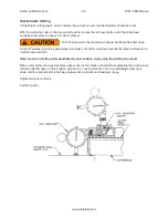
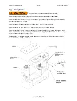
Dial Indicator Setting
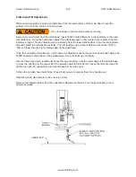
If chip shield, cutting insert, or dial indicator have been moved, the dial indicator should be reset.
With the surfacing cutter in the fore and aft position, press the left travel button until the cutterhead
overlaps a test piece by about 1/2” when rotated.
Turn off all power to the machine whenever handling the cutter head.
Touch off surface, by turning hand wheel clockwise until cutter insert just touches test piece surface when
rotated back and forth.
Note: Do not lower the cutter head directly onto surface, it may chip the cutting tool insert.
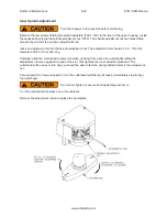
Make a very light cut on your test piece about one inch in. Back out and without adjusting the height press
the dial indicator down on this surface. Adjust it by: Loosing lock nut. Then turn adjusting screw up or
down until the dial indicator is half way between its minimum and maximum range.
Tighten the lock nut firmly.
Set dial to zero.
Summary of Contents for S7M
Page 2: ......
Page 4: ......
Page 8: ...Section 1 Introduction S7M S8M Manual www rottlermfg com 1 4 ...
Page 17: ...Section 2 Installation S7M S8M Manual www rottlermfg com 2 8 ...
Page 18: ...Section 2 Installation S7M S8M Manual www rottlermfg com 2 9 ...
Page 38: ...Section 5 Operating Instructions S7M S8M Manual www rottlermfg com 5 9 ...
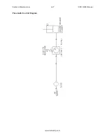
Page 57: ...Section 6 Maintenance S7M S8M Manual www rottlermfg com 6 17 Pneumatic Control Diagram ...
Page 66: ...Section 6 Maintenance S7M S8M Manual www rottlermfg com 6 26 ...
Page 68: ...Section 7 Troubleshooting S7M S8M Manual www rottlermfg com 7 2 ...
Page 71: ...Section 8 Machine Parts S7M S8M Manual www rottlermfg com 8 2 Pneumatic Assembly ...
Page 72: ...Section 8 Machine Parts S7M S8M Manual www rottlermfg com 8 3 Electrical Enclosure ...
Page 74: ...Section 8 Machine Parts S7M S8M Manual www rottlermfg com 8 5 Upper Housing ...
Page 76: ...Section 8 Machine Parts S7M S8M Manual www rottlermfg com 8 7 Spindle Base Front Section ...
Page 77: ...Section 8 Machine Parts S7M S8M Manual www rottlermfg com 8 8 Inner Outer Spindle Assembly ...
Page 78: ...Section 8 Machine Parts S7M S8M Manual www rottlermfg com 8 9 Spindle Base Bushings ...
Page 79: ...Section 8 Machine Parts S7M S8M Manual www rottlermfg com 8 10 Spindle Base Assembly ...
Page 80: ...Section 8 Machine Parts S7M S8M Manual www rottlermfg com 8 11 Left Ballscrew Support ...
Page 81: ...Section 8 Machine Parts S7M S8M Manual www rottlermfg com 8 12 Right Ballscrew Support ...
Page 82: ...Section 8 Machine Parts S7M S8M Manual www rottlermfg com 8 13 Home and Limit Switches ...
Page 83: ...Section 8 Machine Parts S7M S8M Manual www rottlermfg com 8 14 Pendant Assembly ...
Page 84: ...Section 8 Machine Parts S7M S8M Manual www rottlermfg com 8 15 Spindle Base ...
Page 85: ...Section 8 Machine Parts S7M S8M Manual www rottlermfg com 8 16 Chip Shield 14 16 ...
Page 86: ...Section 8 Machine Parts S7M S8M Manual www rottlermfg com 8 17 14 Fly Cutter ...
Page 87: ...Section 8 Machine Parts S7M S8M Manual www rottlermfg com 8 18 Chip Chute ...
Page 89: ...Section 8 Machine Parts S7M S8M Manual www rottlermfg com 8 20 Riser Set ...
Page 90: ...Section 8 Machine Parts S7M S8M Manual www rottlermfg com 8 21 Air Diagram ...
Page 92: ...Section 9 Options S7M S8M Manual www rottlermfg com 9 2 ...
Page 94: ...Section 10 Material Data Safety Sheets S7M S8M Manual www rottlermfg com 10 2 ...
Page 95: ...Section 10 Material Data Safety Sheets S7M S8M Manual www rottlermfg com 10 3 ...
Page 96: ...Section 10 Material Data Safety Sheets S7M S8M Manual www rottlermfg com 10 4 ...


