


Operating Instructions
7
SG80AII Manual
www.rottlermfg.com
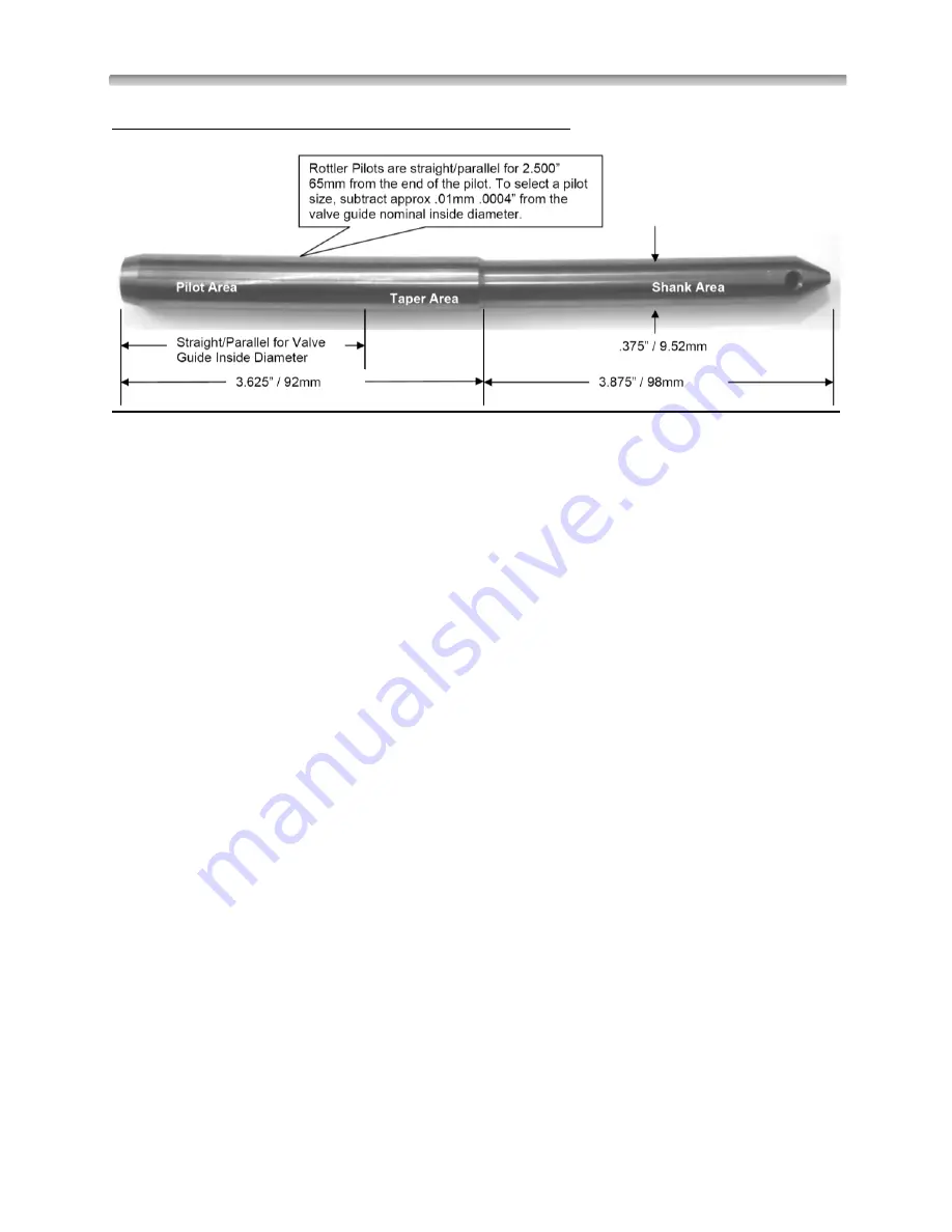
Below is an example of a 9.52mm 0.375” shank diameter pilot:
IMPORTANT:
The centering accuracy and the machining accuracy depend on the pilot tolerance.
We insist on the necessity of using Rottler Fixed pilots.
No other pilots would have the necessary quality for accurate centering.
Aligning Cylinder Heads which have Canted Valve Guides
1-
Install Cylinder Head.
2-
Loosen Pivot Locks and rotate Cylinder Head 180º, so combustion chambers are in up position
and Valve Guides are approximately vertical.
3-
Tighten Fine Adjustment Lock. DO NOT tighten Pivot Locks.
4-
Install two (2) Pilots in exhaust or intake valve guides to be machined. approximately 6.00” to
8.00”
(150 to 200 mm) apart. Install largest size Pilots which will fit into valve guides. Pilots should not
be more than .001 in. (0,03 mm) smaller than valve guides.
5-
Install Canted Alignment Fixture (CANTEDFIX) on high side of Pilots. With Locating Pin pointing
up, clamp Retaining Spring around left pilot and allow Bar to rest against right Pilot.
6-
Slide Bar down Pilots so it is resting on cylinder Head.
7-
Place the digital Level pick up unit on Bar Locating Pin. Rotate Level so it is positioned front to
back (see picture bellow).
8-
Record de tilting of the display panel (upper Right).
9-
Turn the tilt Adjustment handle CLOCKWISE. (Knob is located on right end of Workhead
Assembly.)
10-
First tighten left Pivot Lock; then tighten right Pivot Lock.
11-
Recheck Level and readjust as required.
12-
Remove Level pick up unit from Canted Alignment Fixture and remove Bar.
13-
Place Adjustable Level on one of the Pilots (see picture bellow) and rotate it so it is parallel with
Head (left to right).
14-
Remove Level pick up unit from Pilot and place on Leveling Post located on left-front of Spindle
Housing.
15-
Rotate Level so it is parallel to Cylinder Head (left to right).
16-
Pull down on Eccentric Clamps on the workhead(Release Position).
Summary of Contents for SG80AII
Page 2: ......
Page 12: ...Introduction Safety Installation 9 SG80AII Manual www rottlermfg com Electrical Enclosure ...
Page 49: ...Machine Parts 7 SG80AII Manual Type text www rottlermfg com Type text Base Assembly ...
Page 52: ...Machine Parts 10 SG80AII Manual Type text www rottlermfg com Type text Spindle Assembly ...
Page 56: ...Machine Parts 14 SG80AII Manual Type text www rottlermfg com Type text Transmission Assembly ...
Page 59: ...Machine Parts 17 SG80AII Manual Type text www rottlermfg com Type text Head Support Assembly ...


