background image

Machine Parts 

SG80AII Manual 


[Type text] 

www.rottlermfg.com 

[Type text] 

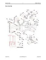
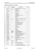
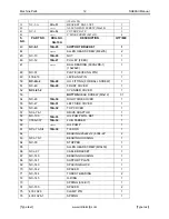
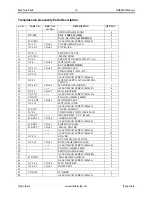
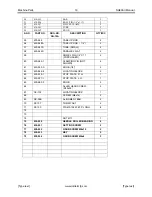
Base Table and Riser Assembly Parts Description 


S. NO. 

PART 

NO. 

DRG NO. 

SG-10A 

DESCRIPTION QTY/M/C 

1.


 430-820-1   

COVER 

PAN 

2.


 NCL 

-99-2   

RISER 

3.


430-822 


BUTTON HEAD SCREW (M6x12) 

4.


5.


 430-821-1   

STOP 

PLATE 

6.


 033-071 


PLATE 

7.


430-830 


VACCUM GAUGE 2.5” STD-B X ¼ NPT 

8.


 430-831 


N-22-SW 

(9301) 

9.


 430-832 


SV-3-M5 

(6817) 

10.


 430-837 


QSS-6 

(153158) 

11.


 430-807 


TOOL 

CABINET 

12.


 430-816 


TOOL 

TRAY 

13.


 430-806 


MOUNTING 

BRACKET 

14.


 430-802 


KNOB 

(M8x25MM 

O.D.) 

15.


 430-817-1   

CLAMP 

PIN 

16.


 430-823 


CLAMP 

LEVER 

17.


NC - 41 


TABLE 

18.


VGS-804 


SPRING WASHER (M8) 

19.


VGS-803 


ALLEN HEAD SCREW (M8x30) 

20.


 430-811 


PLAIN 

WASHER 

(Ø12MM) 

11 

21.


 430-810 


LOCK 

WASHER 

(Ø12MM) 

14 

22.


430-809 


ALLEN HEAD SCREW (M12x70) 

23.


430-812 


ALLEN HEAD SCREW (M12x50) 

24.


430-801-A 10A-1 

CABINET ASSY 

25.


 430-813 


HEX 

SCREW 

(M12x50) 

26.


 430-818 


LEVELING 

BOLT 

(M16x75) 

26A.  430-818-1 


HEX. HEAD SCREW (M16x180) 

27.


430-818A 


HEX NUT (M16) 

28.


 430-819 


PAD 

29.


 430-825 


HANDLE 

30.


 430-827 


MEGNET 

BLOCK 

31.


 430-833 


SPRING 

32.


 430-834 


ROD 

33.


430-835 


FRAME WELDED  

34.


430-838 


ALLEN HEAD SCREW (M5x12) 

35.


430-836 


FOOT SWITCH MTG. BKT 

36.


430-814 


ALLEN HEAD SCREW (M6x20) 

37.


 430-828 


FOOT 

SWITCH 

ASSY 

38.


 430-805 


NUT 

(M5) 

39.


 430-824 


CHIP 

TRAY 

40.


 430-835A   

PAD 

41.


 430-835B   

BUSH 

42.


NCL-98 

10A-2 

AIR FITTING BOX 

43.


44.


 430-826-1   

RUBBER 

SHEET 

45.


430-829-1 


TOOL BOARD (L.H) 

46.


 430-839-1   

PILOT 

STAND 

47.


 033-069 


SUPPORT 

BRACKET 

48.


ALLEN HEAD SCREW (M6x16) 

Summary of Contents for SG80AII

Page 1: ...S AND MAINTENANCE MANUAL MANUFACTURED BY ROTTLER MANUFACTURING LLC 8029 South 200th Street Kent Washington 98032 USA Phone 253 872 7050 Fax 253 395 0230 Website http www rottlermfg com NOTE WHEN ORDERING REPLACEMENT PARTS PLEASE GIVE THE MODEL AND SERIAL NUMBER SEND DIGITAL PHOTO OF PART TO EXPIDITE ORDER ORDER BY PART NUMBER THERE IS A MINIMUM ORDER OF 25 00 ...

Page 2: ......

Page 3: ...nstallation Chapter 2 Control Definition Chapter 3 Operating Instructions Chapter 4 Maintenance Chapter 5 Troubleshooting Chapter 6 Machine Parts Chapter 7 Options Chapter 8 MSDS Individual Chapter Table of Contents are at the front of each Chapter ...

Page 4: ... Safety Instructions for Machine Use 4 Electrical Power 5 Machine Operator 6 Emergency Procedure 7 Air Supply 7 Air Adjustments 7 Float 7 Power Supply 8 Grounding 8 Electrical Enclosure 9 Avoid Accidental Starting 10 Careless Acts 10 Job Completion 10 Replacement Parts 10 Misuse 10 Placement 10 Machine Installation 10 Location 10 Unpacking and Lifting 11 Positioning the Machine 11 Location of the ...

Page 5: ...gital display rpm Tool Storage Cabinet 3 drawer Digital Electronic Level Dial gage for depth control of spindle travel Hex key set Built in Vacuum Tester Spindle diameter 3 150 80mm Maximum Spindle Stroke 8 203mm Maximum Tilt either side of zero 15 degrees Distance from Table to Spindle 19 5 495mm Maximum Cylinder Head Length with 360 rollover fixture 44 1118mm Maximum Cylinder Head Length with di...

Page 6: ...ervice not certified by Rottler Rottler shall not be liable for any consequential direct or indirect damages or for any other injury or loss Buyer waives any right beyond the foregoing warranty to make a claim against Rottler No warranty is provided for any Products not paid in full Merchandise cannot be returned to Rottler without prior approval Customer must contact the Order Department or repre...

Page 7: ...ult in death or serious injury WARNING indicates a potentially hazardous situation which if not avoided could result in death or serious injury CAUTION indicates a potentially hazardous situation which if not avoided may result in minor or moderate injury CAUTION used without the safety alert symbol indicates a potentially hazardous situation which if not avoided may result in property damage This...

Page 8: ...ES performing the intended operation stop using the machine Then contact our service department or ask a qualified expert how the operation should be performed No list of safety guidelines can be complete Every shop environment is different Always consider safety first as it applies to your individual working conditions Use this and other machinery with caution and respect Failure to follow guidel...

Page 9: ...he caution care and knowledge required to safely operate metal cutting tools If the operator is not a skilled machinist he she must pay strict attention to the Operating Instructions outlined in this manual and get instruction from a qualified machinist in both production and operation of this machine The SG80AII machines have the following areas of exposed moving parts that you must train yoursel...

Page 10: ...ource for the SG80AII machine be moisture free Water and oil in the line will result in early cylinder and valve failure The factory recommends installing a water trap at the machine Attach a 100 P S I air source to the appropriate intake in the small enclosure located on the left rear of the machine near the bottom Bellow you will se the Air regulator panel for the different settings on the flout...

Page 11: ...enclosure The connection termination point is located on the left hand side of the electrical panel about half way up Connect L1 to the grey terminal block L2 neutral to the blue terminal block and shop ground to the green and yellow terminal block Attach wire from the grounding rod to the second green and yellow terminal Important Electrically connect in accordance with national and local electri...

Page 12: ...Introduction Safety Installation 9 SG80AII Manual www rottlermfg com Electrical Enclosure ...

Page 13: ...d connection Be certain to use an adequately sized air line permitting proper operation of float Air pressure should never drop below 90 PSI at any time Failure to provide adequate air supply may cause improper floating and clamping At this time some customers will install a T fitting or manifold at the regulator allowing another air hose to be connected providing a connection point for air tools ...

Page 14: ... Base will serve as Leveling Screws while two 2 Screws installed in front corners of Machine Base will serve only as Support Screws Move Machine to desired location and placed leveling bolts over the center hole of the Leveling Pad Be certain to allow sufficient clearance to allow access for leveling and also for connecting air and electrical lines Lower machine onto leveling pads making certain t...

Page 15: ...Introduction Safety Installation 12 SG80AII Manual www rottlermfg com Location of the Shipping Brackets ...

Page 16: ...best to hold nylock locking nut secure on top side and loosen bolt with wrench from underside of clamp plate Required machinist level Starret 98 or better NOTE Rotate Level 180º to check that Level is properly adjusted If Level does not read same in both directions recalibrate level Use the level on the upper float surface level the machine as precisely as possible front to back and side to side L...

Page 17: ...tialization Screen 2 General Information 3 Head Select 3 New 3 Edit Head Model 4 Delete Head 4 Mode Select 4 Programming the vertical stops Dwell Options 5 Homing 5 Building Programs 5 Seat Cutting Mode 5 Setting Zeros 5 Vertical Zero 6 Start the spindle 6 Start Auto Cycle 7 Safety Tips Before Proceed machining 8 Operation Tips before Machining Valve Seats 8 Seat machining Suggested RPM Chart 9 ...

Page 18: ...r must shut down its internal systems before main power is removed from it From any screen press FILE and then EXIT button This will shut down the Rottler program The terminal will show the computer desktop screen Press the Start button in the left hand side of the Start Bar This will bring up the Start Menu Press the Shutdown line at the bottom of the Start Menu This will bring up a Pop Up menu m...

Page 19: ... press the ENTER button to start using the Rottler Program General Information Once selected all operations of the SG80AII can perform are stored in that Cylinder Head model The following is a more detailed list on the head selecting screen Head Select This screen allows you to select create edit or delete a Cylinder Head model This will change the screen to the MODE SELECT Screen New Pressing thi...

Page 20: ...AVE and DONE Delete Head To delete a head select the head from the list on the left Press the DELETE CYLINDER HEAD BUTTON The screen will ask you if you want to delete the Head Select YES or No and then DONE Mode Select One you have selected a block the screen will switch to the MODE SELECT screen This screen contains all the operations of the SG80A can perform There are several modes you can sele...

Page 21: ...ed the reference points may be off position The reference point is set in exactly the same position each time the machine is homed The machine keeps track of these reference positions internally and the operator will not see them Building Programs Seat Cutting Mode Select Cylinder Head and then the valve seat that you will be machining on the control panel This will bring up the seat cutting progr...

Page 22: ...lue Start the spindle Press the Handweel 001 button to put the handwheel in 001 per detent Slowly move the spindle downward until you can hear or see the cutter just touch the valve seat at this point Press your Vertical Zero button here button and verify the zeros on the left lower corner above the Stop Machine button The Vertical zero has now been set From this point on you can star setting the ...

Page 23: ...E Button Start Cutting Height the spindle will go dawn and float for few seconds to the setting that you inner on the display box On this sample the spindle will go down 0 020 before it touching the seat 4 Press the AUTO Button Finish Cutting Depth on the simple you will see on the display box 0 0150 The spindle will start at the programmed RPM The vertical feed will start at the programmed rate i...

Page 24: ...t Angle Cutter to ensure they are sharp firmly attached and are not damaged NEVER force tools when operating Tools will do a better and safer job when operated at speed rate for which they were designed Always turn OFF electrical power when performing service on your machine if service does not require power High Voltage exists inside Electrical Control Enclosure use caution when working on or aro...

Page 25: ...ested RPM Chart VALVE SEAT DIAMETER SPINDLE SPEED INCH METRIC RPM 15 16 24MM 175 1 000 25 4MM 150 1 125 29MM 150 1 250 32MM 125 1 375 35MM 100 1 500 38MM 100 1 625 41MM 100 1 750 44 5MM 100 1 875 47 5MM 75 2 000 51MM 75 2 125 54MM 75 2 250 57MM 75 2 375 60MM 50 2 500 63 5MM 50 ...

Page 26: ...ng knob Adjust the fixture to bring the carbide bit flat against the grinding wheel Make sure the carbide tip face is perfectly parallel to the wheel face by pushing it with the thumb Once a good setting is achieved lock the adjusting knob Before to start the grinding motor move the carbide bit away from the wheel by rotating the tool holder The motor should then be started and the carbide tip fac...

Page 27: ...ases we will install the cylinder head deck side down with the exhaust side of the head against the adjustable stops This is particularly true of wedge style heads It is necessary for the clamps to thrust the cylinder head against the stops when clamped When heads are mounted in this fashion the tallest portion of the combustion chamber will be at the rear of the machine when the head is rotated i...

Page 28: ...er fixed plate on the 360 degree fixture left and right Install the U Clamp you must use the two bolts included with the fixture and make sure is good and tight The cylinder head gasket surface must be against the machined surface of the U Clamp Fixture Slide the stopper rod equally and push the cylinder heads against the stopper rods ...

Page 29: ...st between the cylinder head and the stopper rod not included The Quick Clamp frame is mounted between the trunions and clamped using the clamping plates See Pictures The cylinder head is then held to the frame with the swivel clamp assemblies through the appropriate head bolt holes or used the standard clamp plates ...

Page 30: ...valveseats are facing up Now place the level on a pilot in the cylinder head and position the level to read front to rear Loosen the lock levers on the supports Be certain the fine adjustment lock screw is loosened Coarse adjustment is made by turning the work piece manually until the level reading is within a couple of degrees of the reading on the leveling post Lightly tighten the lock levers on...

Page 31: ...ements of 01mm 0 0004 For practical purposes it is best to select a pilot that is a small amount less than the nominal size of the valve guide approx 01mm 0 0004 is recommended between the pilot size and the valve guide nominal size This clearance allows the pilot to enter all the guides in a cylinder head as some valve guides may be smaller than their minimum tolerance Most new valve guides are m...

Page 32: ...guides 5 Install Canted Alignment Fixture CANTEDFIX on high side of Pilots With Locating Pin pointing up clamp Retaining Spring around left pilot and allow Bar to rest against right Pilot 6 Slide Bar down Pilots so it is resting on cylinder Head 7 Place the digital Level pick up unit on Bar Locating Pin Rotate Level so it is positioned front to back see picture bellow 8 Record de tilting of the di...

Page 33: ...display unit indicate 0000 18 Push up on Lock Position right Upper Eccentric Clamp first and then lock left Lower Eccentric Clamp NOTE The Workhead is now aligned with Canted Valve Guides The alignment fixture will helps to establish the front to back alignment on canted valve cylinder heads CANTEDFIX ...

Page 34: ...re drill with valve guide by inserting core drill pilot in guide as head of machine is floated and centered Push green button to start the spindle verify correct rotation Operate at 240 RPM feed with moderate pressure until it clears the bottom of the guide Raise Quill to bring core drill above upper end of valve guide Stop spindle by pushing red button 4 Select and install correct reamer Repeat s...

Page 35: ...tton until you get contact on valve seat and then set Vertical Zero Touch inside the Finish Cutting Height box and inner the total depth of the valve seat that you will be installing remember this value it will be a negative number or use the following alternative method NOTE See Seat and Guide Catalog for suggesting tools to perform this operation Set spindle RPM at approximately 80 120 RPM and F...

Page 36: ...p holder the carbide bit s cutting edge should just touch the micrometer spindle Once in contact with the micrometer spindle the carbide tip should not be moved at all If this is not observed the cutting edge may be damaged and the resulting surface quality when machining will be deteriorated Tapping Operations Place the Jacobs chuck or Collet Holder in the spindle as explained previously Install ...

Page 37: ...uide to achieve a concentric seat Cut seat only enough to clean up surface Too much cutting will sink the valve too far in the head Many operators prefer to use the spindle fine feed when machining seats as extreme control of spindle down feed can be accomplished The capacity of the Rottler SG7 SG8 SG80AII SG9 associated with a complete tooling range allow working on seats of diameters between 14 ...

Page 38: ...ndle has been engineered to allow ultra fast tooling changes Make sure the that spindle spring free locking nut is in the off lock position line up the two ears of the spindle adapter and insert into the spindle ISO 30 taper The locking nut automatically will be on the lock position to remove turn the self locking nut to the left position hold the spindle adapter it may drop on the machine table D...

Page 39: ...er about in to the pilot shank release the sleeve to the upper position to achieve perfect centering according to the position of the pilot and lower the toolholder into the pilot manually until reach the proper height or until the carbide tip is a few thousands from making contact on the valve seat Do not make contact with the seat surface the work head should be floating at all the time for few ...

Page 40: ... level assembly is referenced to the spindle via the level pin It is there for important to check alignment of pin in reference to the spindle This is accomplished by mounting a magnetic base dial indicator to the machine spindle and sweeping the pin vertically by raising or lowering spindle to check alignment Pin alignment should be checked in two positions at 90 degrees to each other If the pin ...

Page 41: ...Bars 2 Take the workhead to one end of the of the upper floating surfaces Left or Right side float the workhead and pull it against the front on the T Slatted guide surfaces then loose the set screws of the eccentric pin to increase clearance by using a feeler gage of 0 008 to 0 010 0 20mm to 0 25mm in between the T slotted guide surfaces of the upper base and the eccentric ball bearing see fig be...

Page 42: ...et should be 0 010 0 20mm whereas the clearance between the right valve plunger and the food pedal bracket should be 0 039 0 75mm This can be achieve by loosing the two fixing screws and the adjusting the valve mounting bracket Tighten back the bracket see fig below When the food pedal is pressed remove the black air tube from the left port and it should be a full air flow whereas when you remove ...

Page 43: ...Parts 4 Base Table and Riser Assembly 4 Base Table and Riser Assembly Parts Description 5 Base Assembly 7 Base Assembly Parts Description 8 Spindle Assembly 10 Spindle Assembly Parts Description 11 Transmission Assembly 14 Transmission Assembly Parts Description 15 Head Support Assembly 17 Head Support Assembly Parts Description 18 Decimal to Metric Conversion Chart 20 ...

Page 44: ...or Large diameter milling Head 3 8 insert MHS 250 Fixed Double Replaceable Insert Milling Head Screws for Small diameter milling Head 1 4 insert S1032 250 BH375R1 and BH600R1 Tip Holder Looking Screw 10 32 X 1 4 Req 2 S250 28 250 BH375WR1 Tip Holder Looking Screw 1 4 28 X 1 4 Req 2 S1032 437 TH1999 Adjusting Screw 10 32 X 7 16 S1032 375 TH2000 Adjusting Screw 10 32 X 3 8 S1032 500 TH2001 Adjusting...

Page 45: ...esigned for a life time of precision machining The part number of the pilot represents the actual diameter in metric of the straight parallel part of the pilot where the pilot fits into the valve guide For example FCP0700 means that the diameter of the part of the pilot that goes into the valve guide is 7 00mm 0 2756 FCP1270 means that the diameter of the part of the pilot that goes into the valve...

Page 46: ...Machine Parts 4 SG80AII Manual Type text www rottlermfg com Type text Machine Parts Base Table and Riser Assembly ...

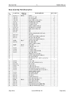
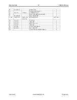
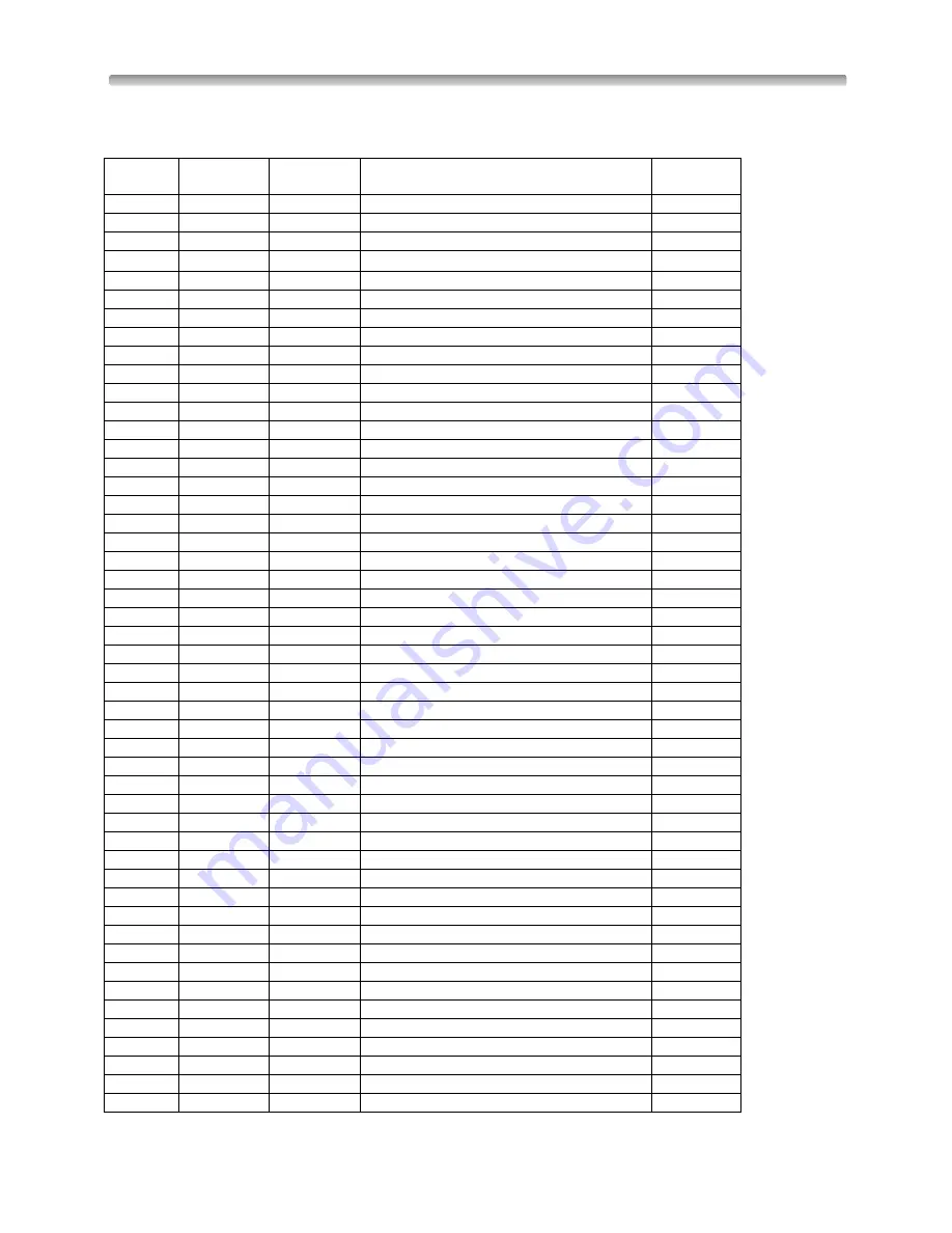
Page 47: ...SCREW M8x30 4 20 430 811 PLAIN WASHER Ø12MM 11 21 430 810 LOCK WASHER Ø12MM 14 22 430 809 ALLEN HEAD SCREW M12x70 3 23 430 812 ALLEN HEAD SCREW M12x50 7 24 430 801 A 10A 1 CABINET ASSY 1 25 430 813 HEX SCREW M12x50 4 26 430 818 LEVELING BOLT M16x75 5 26A 430 818 1 HEX HEAD SCREW M16x180 1 27 430 818A HEX NUT M16 6 28 430 819 PAD 6 29 430 825 HANDLE 2 30 430 827 MEGNET BLOCK 2 31 430 833 SPRING 2 3...

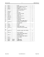
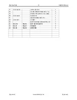
Page 48: ...6 NUT M6 2 57 PLAIN WASHER 6MM 2 58 LOCK WASHER 6MM 2 59 60 61 62 63 430 839 2 SUPPORT PLATE 1 64 430 839 3 RACK INSERT HOLDER 1 65 430 839 4 NAME PLATE 2 66 101A 109 VACUUM PAD 1 67 101A 110 VACUUM PAD 1 68 101A 111 VACUUM PAD 1 69 101A 112 VACUUM PAD 1 70 101A 113 VACUUM PAD 1 71 101A 114 VACUUM PAD 1 72 101A 115 VACUUM PAD 1 73 430 815 S 1 SHIPING CLAMP NOT SHOWN 2 74 430 841 PIN NOT SHOWN 4 75...

Page 49: ...Machine Parts 7 SG80AII Manual Type text www rottlermfg com Type text Base Assembly ...

Page 50: ...ING PIN 1 19 430 522 PIN HOLDER 1 20 GRUB SCREW M6x6 1 21 NC 27 10A 8 WASHER 1 22 CIRCLIP EXT 1 23 NC 113 SPACER 2 24 NC 109 CLAMP ARM 2 25 NC 110 CLAMP ARM TIE ROD 1 26 NC 111 SQUARE BOLT 2 27 SPRING 1 25x12x9x41 2 28 ALLEN HEAD BOLT M8x90 2 29 PLAIN WASHER 2 30 PNUMATIC CYL ADVU 63 10 P A 156559 1 31 NC 114 CYL PAD 1 32 NC 108 CYL MOUNTING PLATE 1 33 430 629 2 PIVOT PIN 1 34 NC 25 1AC CABLE CLIP...

Page 51: ... KNOB 1 4 x O D 1 1 60 430 629 1 CLAMP PIN 1 61 430 510 ECCENTRIC COLLAR 2 62 430 552 TAPER PIN 2 63 ALLEN HEAD SCREW M4x12 2 64 430 514 S 3 SHIPPING CLAMP BRACKET NOT SHOWN 2 65 NC 34 CLAMP 1 66 430 516 LEVER 1 67 430 517 KNOB M8x50 LONG 1 68 430 514 S 1 CLAMP PLATE NOT SHOWN 1 69 70 430 514 S 2 SHIPPING CLAMP NOT SHOWN 2 71 NC 115 1 PIVOT SUPPORT 1 72 ALLEN HEAD SCREW M8x40 2 73 NC 119 BEARING B...

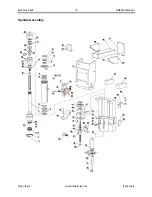
Page 52: ...Machine Parts 10 SG80AII Manual Type text www rottlermfg com Type text Spindle Assembly ...

Page 53: ...16 2 12 430 623B F PT GRUB SCR M5x6 2 13 NC 33 STOP PLATE LOCK NUT 1 14 430 603A GRUB SCREW M6x6 2 14A 430 603B PLUG 2 15 430 603 LOCK NUT 1 16 430 601 1 END STOPPER 1 17 KS 08 06 COVER 1 18 KS 08 05 PIN 1 19 KS 08 04 SPRING 1 20 KS 08 01 STOP PIN 1 21 NC 46 10A 18 BACK COVER 1 22 NC 16 1 10A 19 EXT BLOCK RIGHT 1 23 NC 15 1 10A 36 SPINDLE HOUSING 1 23A 430 614S SHIPPING CLAMP NOT SHOWN 1 24 430 62...

Page 54: ...EW 1 51 NC 40 10A 29 FRONT COVER 1 52 NCL 81 2 CYLINDER COVER 1 53 BUTTON HEAD SCREW M5x12 31 54 NC 48 10A 30 RIGHT SIDE COVER 1 55 NC 47 10A 31 LEFT SIDE COVER 1 56 NC 49 10A 32 TOP COVER 1 57 NCL 76 1 DRIVE ADAPTOR 1 58 NC 103 10A 33 OIL PUMP MTG BKT 1 59 055A 337 10A 34 LUB FEEDER 1 60 OIL PUMP 1 61 NCL 73 S 1 10A 39 TIE ROD 1 62 BEARING 20x42x12 6004 2Z 2 63 NCL 70 1 BEARING HOUSING 1 64 NC 93...

Page 55: ...7 430 1049 B LEVEL BLOCK 1 78 ALLEN HEAD SCREW M3 x 12 2 79 DOWEL PIN Ø3 16 x 3 4 LONG 1 80 430 1049C SLIDE PIN 1 81 GRUB SCREW M5 x 16 1 82 430 1025 CLAMP 1 83 BUTTON HEAD SCREW M5 x 10 1 84 NC 13 1 10A 35 EXT BLOCK LEFT 1 85 NC 31 10A 37 SPACER 1 86 NC 50 10A 38 STOPPER 1 ...

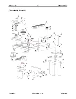
Page 56: ...Machine Parts 14 SG80AII Manual Type text www rottlermfg com Type text Transmission Assembly ...

Page 57: ...IVE 1 19 ALLEN HEAD SCREW M10x25 4 20 NC 38 10A 47 MTG BRACKET 4 21 VGS 731 ALLEN HEAD SCREW M10x30 4 22 VGS 732 PLAIN WASHER 10MM 8 23 NC 24 III 10A 49 MOTOR PULLEY 1 24 NC 133 MOTOR FLANGE 1 25 ALLEN HEAD SCREW M8x45 1 26 430 720 COVER SUPPORT 4 27 NC 54 TIMING BELT HTD 1200 8M 30 1 28 VGS 753 GRUB SCREW F PT M6x8 3 29 430 PP 12 10A 50 LARGE SPACER 2 30 ALLEN HEAD SCREW M8x90 2 31 430 PP 5 10A 5...

Page 58: ...PIN Ø6x35 2 51 NC 152 10A 46 SUPPORT FLAT 1 52 BALL BEARING 6206 2RS 1 53 430 534 B BRG SUPPORT 1 S NO PART NO DRG NO SG 10A DESCRIPTION QTY M C 54 NC 153 FLANGE 1 55 NC 154 SPACER 2 56 NC 156 KEY 1 4x1 1 4 1 57 NC 157 SPACER 1 58 430 728 LOCATING BUSH 1 59 430 730 INT CIRCLIP 1 60 ALLEN HEAD SCREW M4x16 4 ...

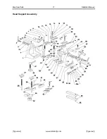
Page 59: ...Machine Parts 17 SG80AII Manual Type text www rottlermfg com Type text Head Support Assembly ...

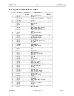
Page 60: ...100 057 4 17 430 919 PLUNGER 4 18 430 915 PLATE 4 19 VGS 960 CAP BLACK 4 20 430 936 ALLEN HEAD SCREW M6x20 2 21 SF 108 FLAT 2 22 23 430 914 GUIDE ROD 1 24 SF 112 HOLDER RIGHT 1 25 430 907 BEARING BUSH RIGHT 1 26 430 934 SPACER 1 27 430 933 COLLAR 1 28 430 929 ARM 1 29 VGS 928 PIN 1 8 x5 8 1 30 430 927 CLAMP 1 31 430 904 ROLL PIN 1 8 x3 4 1 32 430 548 RETAINING RING 1 32A 430 550 THRUST BEARING 12x...

Page 61: ...L FLAT 2 59 DOWEL PIN 1 4 X 1 PURCHASED 2 60 430 965 1 CLAMPING PIN NOT SHOWN 4 61 430 942 A KNOB 1 4 2 62 430 944 II LOCATING BLOCK 2 63 430 935 I STOP PLATE R H 1 64 430 937 I STOP PLATE L H 1 65 430 962 2 KNOB 2 66 ALLEN HEAD SCREW M12x25 2 67 NC 105 LOCATING BLOCK 1 68 SCREW M6x16 2 69 NC 59B ALIGNMENT BAR 2 70 SF 107 TOMMY NUT 2 71 SF 130 PIN Ø0 156 x0 970 LONG 2 72 73 74 NUT M10 1 75 430 950...

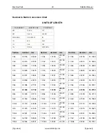
Page 62: ...987 5 2 1 16 2 0625 52 3875 5 64 0 0781 1 9844 1 5 64 1 0781 27 384 4 2 5 64 2 0781 52 7844 3 32 0 0938 2 3813 1 3 32 1 0938 27 781 3 2 3 32 2 0938 53 1813 7 64 0 1094 2 7781 1 7 64 1 1094 28 178 1 2 7 64 2 1094 53 5781 1 8 0 1250 3 1750 1 1 8 1 1250 28 575 0 2 1 8 2 1250 53 9750 9 64 0 1406 3 5719 1 9 64 1 1406 28 971 9 2 9 64 2 1406 54 3719 5 32 0 1563 3 9688 1 5 32 1 1563 29 368 8 2 5 32 2 1563...

Page 63: ...2 25 64 2 3906 60 7219 13 32 0 4063 10 318 8 1 13 32 1 4063 35 718 8 2 13 32 2 4063 61 1188 27 64 0 4219 10 715 6 1 27 64 1 4219 36 115 6 2 27 64 2 4219 61 5156 7 16 0 4375 11 112 5 1 7 16 1 4375 36 512 5 2 7 16 2 4375 61 9125 29 64 0 4531 11 509 4 1 29 64 1 4531 36 909 4 2 29 64 2 4531 62 3094 15 32 0 4688 11 906 3 1 15 32 1 4688 37 306 3 2 15 32 2 4688 62 7063 31 64 0 4844 12 303 1 1 31 64 1 484...

Page 64: ...500 44 450 0 2 3 4 2 7500 69 8500 49 64 0 7656 19 446 9 1 49 64 1 7656 44 846 9 2 49 64 2 7656 70 2469 25 32 0 7813 19 843 8 1 25 32 1 7813 45 243 8 2 25 32 2 7813 70 6438 51 64 0 7969 20 240 6 1 51 64 1 7969 45 640 6 2 51 64 2 7969 71 0406 13 16 0 8125 20 637 5 1 13 16 1 8125 46 037 5 2 13 16 2 8125 71 4375 53 64 0 8281 21 034 4 1 53 64 1 8281 46 434 4 2 53 64 2 8281 71 8344 27 32 0 8438 21 431 3...

Page 65: ...Type text www rottlermfg com Type text 4 4 31 32 0 9688 24 606 3 1 31 32 1 9688 50 006 3 2 31 32 2 9688 75 4063 63 64 0 9844 25 003 1 1 63 64 1 9844 50 403 1 2 63 64 2 9844 75 8031 1 1 0000 25 400 0 2 2 0000 50 800 0 3 3 0000 76 2000 ...

Page 66: ...Options 1 SG80AII Manual www rottlermfg com Options Options and Tooling are in separate manuals ...

Page 67: ...Material Safety Data Sheets 1 SG80AII Manual www rottlermfg com Material Safety Data Sheets Additional MSDS documents located on manual CD ...

Reviews: