Operating Instructions
17
SG9M Manual
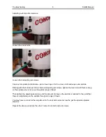
Release your hands from Work Head to allow spindle to stabilize and Cutter to center itself on the valve
guide. Release Foot Pedal.
Spherical pneumatic switch should bee on the OFF position all the time that you be machining the valve
seat, this will give you a positive Live centering system
Note:
Using the left hand on the work head, guide the work head and with the right hand on the main
Hand wheel, lower spindle into the valve guide. This will allow you easy positioning the carbide pilot into
the valve guide and with the Right hand on the main had wheel lower the pilot into the valve guide (Left
Pedal needs to be depress all the time when you centering in the valve guide).
If the pedal is released too quickly, the float head may bounce. True centering may not be achieved if
this happens. Slowly releasing the air float pedal gives the best results. Removing your hands completely
from the work head during the final seconds of centering will insure that you do not negatively influence
centering accuracy.
DO NOT depress Foot Pedal while spindle is on the ON position, as this will change Machine and
Cylinder Head alignment
Once that you achieve seat high; set dial indicator for feed depth to zero, being certain the indicator has
sufficient travel to allow the proper depth of cut.
Cut seat only enough to clean up surface. Too much cutting will sink the valve too far in the head. Many
operators prefer to use the spindle fine feed when machining seats as extreme control of spindle down
feed can be accomplished.
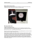
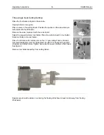
Spherical Pneumatic Looking System
Be sure to turn the Spherical pneumatic switch is on the
ON
position;
this will allow you to align the pilot on the same axis that the valve
guide is set. It will be easy to go into the valve guide.
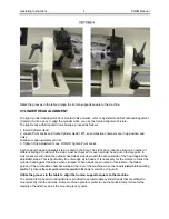
Most machining operations require the spindle to be directly centered
over the work to be performed. This is usually accomplished by air
floating the work head by depressing the left foot pedal above the area
to be machined; then manually lowering the pilot to the valve guide,
once that you have the carbide Pilot about ½” (12.70mm) in to the
valve guide
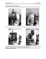
At this point release the Spherical pneumatic switch to the
OFF
position
and bring the pilot into the valve guide manually until reach the proper
height or until the carbide tip is a few thousands from the valve seat
face.
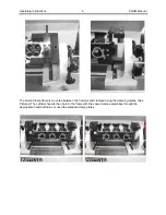
Let Workhead flow for few seconds to achieve maximum alignment
over the pilot.
Summary of Contents for SG9M
Page 2: ......
Page 12: ...Introduction Safety Installation 9 SG9M Manual ...
Page 14: ...Introduction Safety Installation 1 SG9M Manual ...
Page 15: ...Control Definitions 1 SG9M Manual Chapter 2 Control Definitions SG9M Controls ...
Page 16: ...Control Definitions 1 SG9M Manual ...
Page 35: ...Operating Instructions 1 SG9M Manual ...
Page 39: ...Maintenance 1 SG9M Manual ...
Page 45: ...Troubleshooting 1 SG9M Manual ...
Page 51: ...Machine Parts 6 SG9M Manual WORKHEAD ASSEMBLY ...
Page 54: ...Machine Parts 9 SG9M Manual SPINDLE ASSEMBLY ...
Page 57: ...Machine Parts 12 SG9M Manual TRANSMISSION ASSEMBLY ...
Page 59: ...Machine Parts 14 SG9M Manual HEAD SUPPORT ASSEMBLY ...
Page 62: ...Machine Parts 17 SG9M Manual SG9M Pneumatic Drawing ...
Page 70: ...Options 1 SG9M Manual Options ...
Page 71: ...Options 2 SG9M Manual ...

