9 Options
32
4000021245
9
Options
9.1
Emergency brake release
Materials:
•
3-port/2-way control valve (12)
Hydraulically operated, suitable for Qmax according to
technical data considering max allowed pressure and
max return flow pressure.
•
Auxiliary hydraulic system or hand pump (10)
Max stroke volume of hand pump 4.3 in
3
. Volume flow
and required pressure of auxiliary hydraulic.
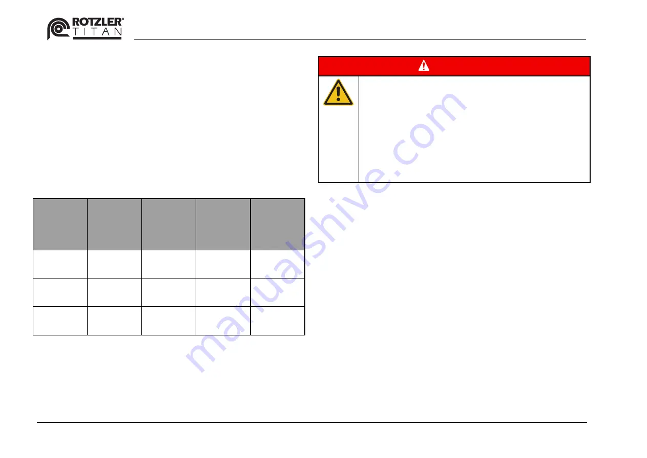
Winch
type
min. vol-
ume flow
[US gpm]
max.
volume
flow [US
gpm]
min.
pressure
[psi]
max.
pressure
[psi]
TI 5
GM107
0.9
1.1
580
730
TI 5
GM085
0.9
1.1
580
730
TI 5
PM049
1.2
1.3
870
1150
•
Check valve (13)
Cracking pressure 15 psi, suitable for Qmax according
to technical data considering max allowed pressure and
max return flow pressure.
DANGER!
Risk of injuries!
Danger due to dropping load!
The load can drop uncontrollably if the volume
flow of the auxiliary hydraulic is too high.
The load can drop uncontrollably if the pressure at
the auxiliary hydraulic raises too quickly.
The load can drop uncontrollably if the motor cavi-
tates.
Installation:
Install 3-port / 2- way control valve (12), Auxiliary hydraulic
system or hand pump (10) and Check valve (13) according
to hydraulic diagram.
When oil is supplied from the auxiliary hydraulic or the
hand pump to the emergency brake release, it flows into
the main circuit through an orifice inside the motor housing.
To avoid overflow of the main tank the auxiliary hydraulic or
the hand pump shall be connected to the same tank.


