background image


7

  5.

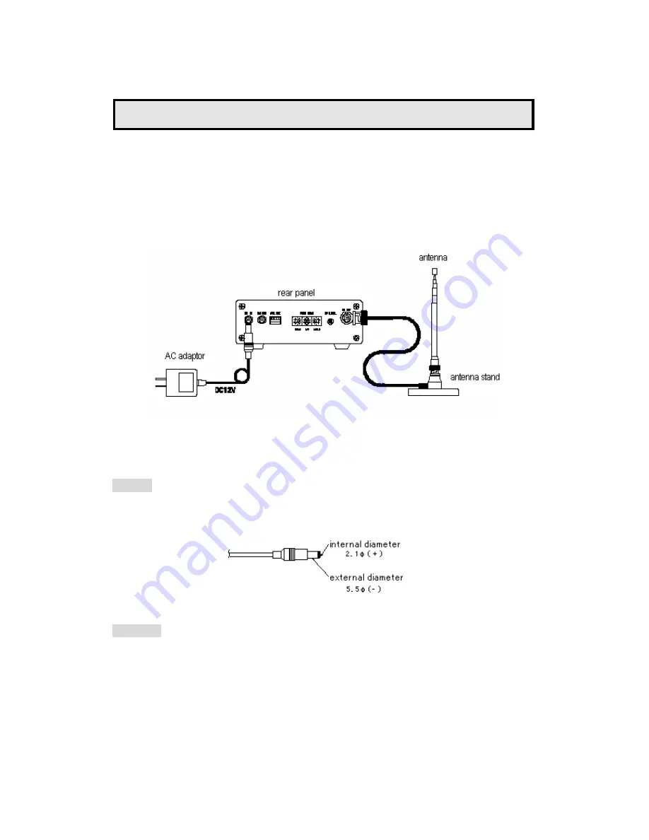
How to Connect 


1)  Connect the AC adaptor contained in the accessory kit to DC IN (

) of the main body. 

2)  Set the antenna attached to the antenna stand and connect a coaxial cable to the RF OUT (

of the main body. 

3)  Turn upward the power switch on the front panel. Power LED lights up and the FM transmitter 

starts to operate.   


Use a DC plug specified below or a PCAB-02 cable (option), when supplying power to external 

equipments from this transmitter. 


DC plug


Attention! 


Check the polarity (+,-) before connecting the cable. 


If you supply excess current (over 300mA) from this transmitter to the external equipment, the 

power will be shutdown automatically.   


In the case of this happening, disconnect the power supply cable for the external equipment and 

turn the power off. Leave it for a while and turn the power switch on. 


Summary of Contents for YS-1010S

Page 1: ...Ver 1 03 2004 07 zip 158 0082 6 40 10 todoroki setagaya ku tokyo japan Phone 81 3 3703 1211 Fax 81 3 3703 1215 ROUGH AND READY INC URL http www randr co jp ...

Page 2: ...apparatus to rain or moisture when installed outdoors 5 Do not give abnormal voltage over the permissible range when you input signals 6 In case you open the covers of the transmitter disconnect the power adaptor first and be careful not to touch and damage the parts inside the transmitter during the manipulation Key features Small sized and high spec in design and by virtue of its low power consu...

Page 3: ...or the visually handicapped 2 Composition The composition of this unit is shown below Please check to ensure whether you have all required components No Name Quantity Specifications 1 YS 1010S Mainbody 1 2 Connector 1 MOLEX 5051 04 for synchronous control 3 Terminals 5 MOLEX 5159 for synchronous control 4 AC adaptor 1 DC12V output 5 Antenna holder 1 With magnets BNC connector type 6 Antenna 1 Rod ...

Page 4: ...within the range of 0 5Vp p 6Vp p approximately Preset at input level of 2Vp p and 75KHz deviations at the time of shipment Composite input For input from external sources using stereocodic signals and closed caption signals Input 2Vp p for stereocodic signal and the transmitter outputs 75KHz deviations Input 0 2Vp p for closed caption signal and the transmitter outputs 7 5KHz deviations Internal ...

Page 5: ...r is turned on 4 Rear Panel DC input A terminal for supplying power from an external source Connect the AC adaptor contained in the accessory kit If you use other power supplies verify the input voltage range DC11 DC18V and the polarity Please choose a power source with the least noise Use a DC jack of 5 5mm external diameter and 2 1mm internal diameter for connection DC output Output voltage will...

Page 6: ...setting switch Set up a transmission frequency 3 digits by a step of 0 1MHz and within the range of 76 0 90 0MHz RF LEVEL adjustment Adjust the transmitter s output level It increases up to 30dB as you turn the adjustor clockwise RF OUT connector The output connector BNC receptacle of the transmitter External equipment such as an antenna a booster and a leaky coaxial cable can be connected Use a c...

Page 7: ...er starts to operate Use a DC plug specified below or a PCAB 02 cable option when supplying power to external equipments from this transmitter DC plug Attention Check the polarity before connecting the cable If you supply excess current over 300mA from this transmitter to the external equipment the power will be shutdown automatically In the case of this happening disconnect the power supply cable...

Page 8: ... B to Analog input Right red two channel mixer output will be transmitted as monaural broadcast Transmit the composite input For transmission of the composite input yellow the transmitter s audio characteristics are determined by the signal characteristics of the connected composite input since VCO will be directly modulated to FM bypass those of input filter pre emphasis circuit stereo multiplexe...

Page 9: ...For slave equipment place the jumper plug between pins 1 and 2 of the JP1 inside the main body How to set up the slave equipment 1 Disconnect the AC adaptor Remove the 4 screws specified below with a screwdriver and pull up the cover Pull up the cover vertically L IN R IN FM TRANSMITTER YS 1010S LOCK COMP INT MON ST POWER Remove the screws in the same place on the back side Remove the screws in th...

Page 10: ...10 Equivalent circuit of synchronous control Replace the jumper from3 4 to 1 2 ...

Page 11: ... the synchronous control N Attention Getting the reduction of clock radiation noise from the connecting cable for synchronous control the shortest cabling of sealed cables or coaxial cables e g 1 5D2V will be most desirable ...

Page 12: ...o of modulation distortion 0 4 TYP S N ratio 60dB TYP Stereo separation 46dB TYP Stability of pilot signal 19KHz 0 5Hz or less Pilot signal phase difference 5 or less Audio input power level 750mVrms VR center 12dB 8dB variable input impedance 10KΩ or more Composite input 2Vp p input impedance 1KΩ or more Optional functions Synchronized CLK input output PLL Locked indicator Red LED Stereo Indicato...

Page 13: ...13 10 Outside drawings DC OUT 11 18V DC IN 0 1 1 10 SYN CLK FREQ MHz RF LEVEL RF OUT L IN R IN FM TRANSMITTER YS 1010S LOCK COMP INT MON ST POWER FM TRANSMITTER MADE IN JAPAN S N 03A00100 mm ...

Page 14: ...mbers The cost of transportation and lodging of our personnel for providing services at your site is not covered by this warranty services Product name Stereo FM Transmitter YS 1010S Purchase date YY MM DD 2004 Product number First Name Family Name Postal code Phone Address E mail Inquiries If you would like to make any inquiry or to give us your opinion about our products please contact the follo...

Reviews: