ASSEMBLY
1.
Using the crank handle, raise the lift carriage up until it just
contacts the O-rings at the top of the shafts.
2.
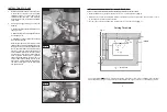
With the router lift propped up on blocks (Fig 1) and the
cam lock open, slide the router all the way down through the
center of the router lift until it contacts the back plate. The
router’s collet can extend down through the center hole in
the base plate. Rotate the router until the switch controls on
the router are in a convenient position, back the router up
from the back plate about 1/16” and close the cam lock clamp.
If the clamp seems too loose or the router moves while being
used or the clamp won’t close, go to step 3 to adjust the
cam lock clamp; otherwise, go to step 4.
3.
To adjust the cam lock clamp, use a 7/16 wrench to loosen
or tighten the lock nut holding the cam lock clamp (Fig 2). A
small adjustment should be all that is needed. Test and
repeat in small increments until a correct fit is achieved.
Clamp router in place as described in step 2.
4.
The lift is now ready for your router table. The Rousseau Router Lift is designed to fit Rousseau router tables,
Rousseau router table tops and is interchangeable with Rousseau Deluxe Base Plates. See “Installing Base
Plate into a Blank Table Top” on next page to make your own router table.
PARTS INCLUDED
ROUTER LIFT PLUS
Height Adjustment Wrench
9” x 12” Phenolic Resin Base Plate
4-1/16” Dia. Red Insert Ring Ring
2-7/8” Dia. Grey Insert Ring
Starter Pin
LEVELING SYSTEM
6 Brass Inserts
6 Nylon Thumb Screws
CORNER SNUGGERS
4 Corner Snuggers
4 screws
4 nuts
Note: Double stick tape may be substituted for clamps if necessary. Use 2” wide tape the full length of ‘L’ jigs.
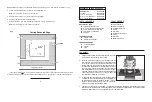
4. Cut the thru hole following the jigs with 1/2” dia. straight flute bit.
Note: To minimize chip out use a up cut spiral bit.
5. Release clamps and move ‘L’ jigs out 3/8” all around (Fig. 2).
6. Re-clamp jigs and set router bit depth to 5/16”.
7. Rout out rabbet 3/8” W X 5/16” D following the jigs with 1/2” dia. straight flute bit..
Note: To minimize chip out, use a down cut spiral bit.
* The 3” figure relates only to a 6-1/2” diameter router base. If you have a router base of a different size your offset
will also be different. To figure out the distance needed between the ‘L’ jigs and the cut, use the following formula:
Cutting Rabbeted Edge
Fig. 2
SUGGESTED ROUTER BIT SPEEDS
BIT DIAMETER
MAX. SPEED
1” (25mm)
24,000 RPM
1-1/4” - 2” (30-50mm)
18,000 RPM
2-1/4” - 2-1/2” (55-65mm)
16,000 RPM
3” – 3-1/2” (75-90mm)
12,000 RPM
( Diameter of Base - 1/2”)
2
TOOLS NEEDED
7/16 End Wrench
1/8 Hex Key Wrench
Phillips Screw Driver
Router
Router Bit
Hand Drill or Drill Press
Clamps
Router Bit
Mallet or Hammer
Fig. 1


