INSTALLING BASE PLATE INTO A BLANK TABLE TOP
If you do not have our Base Plate Installation Kit (3509-T), follow the instructions below.
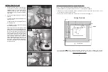
1. Make two hardboard ‘L’ jigs approximately 18-1/4” x 26” - outside dimensions (Fig. 1).
2. Decide where you want the base plate located in the table and mark its outer edges. Then measure in 3/8” in
on each edge for the location of the thru hole.
3. Lay the ‘L’ jigs on table and clamp them in place offset 3”
*
from the thru hole (Fig. 1).
Cutting Thru Hole
Fig. 1
INSTRUCTIONS FOR USE
1.
With the adjustment handle in the hex socket
in the middle of the dial, turn the handle
clockwise to raise your router and counter-
clockwise to lower the router. One revolution
moves the router 1/16”. Remove handle before
using router.
2.
If bit height changes during use, check the
following:
a. Make sure collet is tight and router bit is not
slipping in collet.
b. Make sure cam lock clamp is tight and router
is not slipping in lift.
c. Depending on usage, thread tension needs
to be reset periodically.
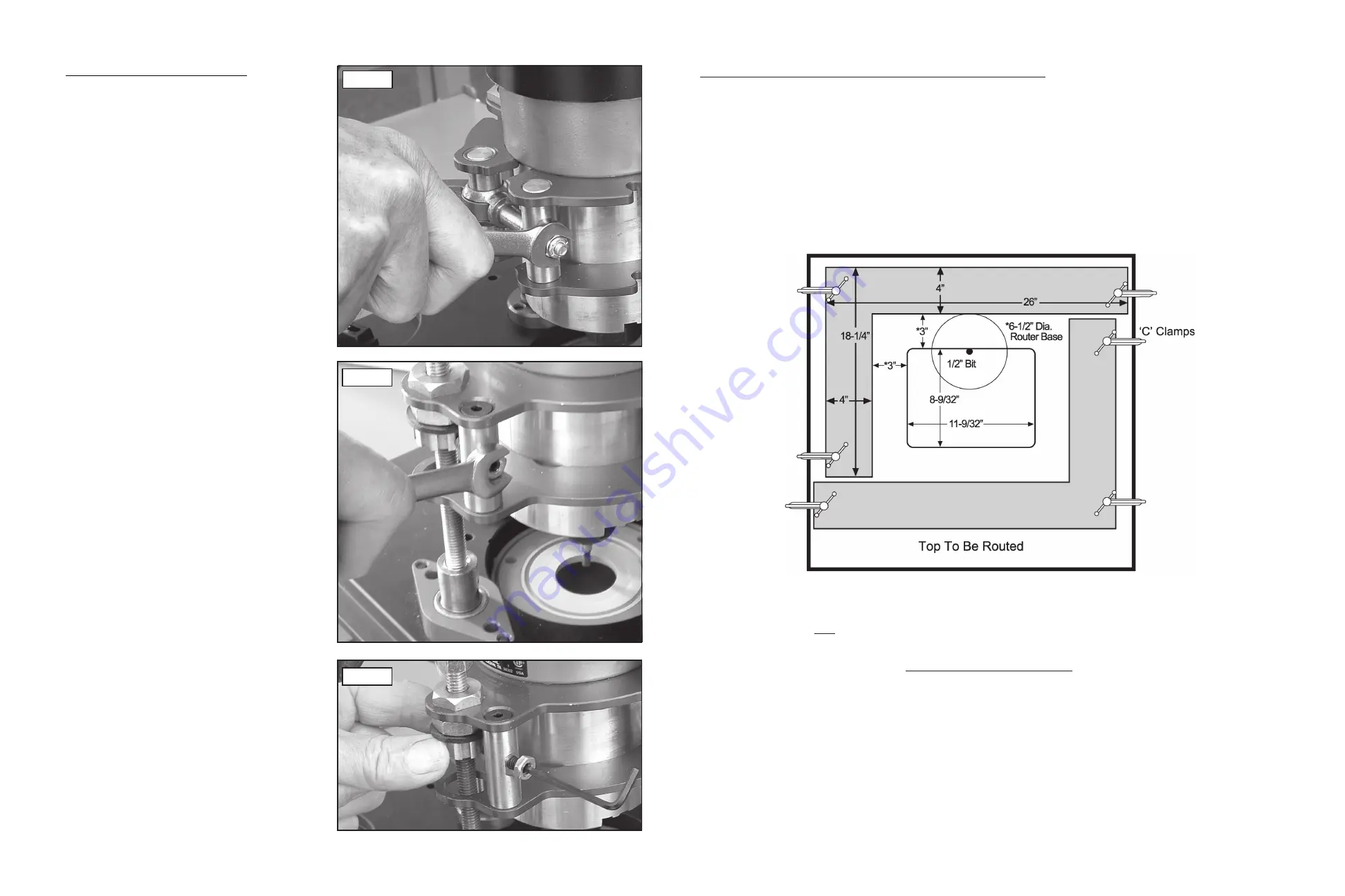
Reset thread tension by first turning the lift
upside down on a table with the adjustment rod
facing you. Using a 7/16 wrench, (Fig. 3) loosen
the 1/4” hex nut located on the side of the brass
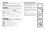
post. Next, use a 1/8” hex key wrench to back
out the setscrew inside the nut until the vertically
grooved brass collar can be turned (Fig. 4).
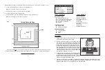
Then, rotate this brass collar so it tightens
against the rubber washer. Note: a drop of oil
on the rubber washer eases rotation of the
brass collar. Finally, tighten the setscrew into
one of the vertical grooves on the brass collar
and tighten the nut.
* The 3” figure relates only to a 6-1/2” diameter router base. If you have a router base of a different size your offset
will also be different. To figure out the distance needed between the ‘L’ jigs and the cut, use the following formula:
( Diameter of Base - 1/2”)
2
Fig. 2
Fig. 3
Fig. 4


