9
S
ection
3 — A
SSembly
& S
et
-U
p
Attaching the tongue
1.
Remove the two hex bolts and lock nuts on the front of the
reservoir tank.
NOTE:
The hardware for attaching the tongue to the reservoir
tank is already inserted into the reservoir tank brackets.
2.
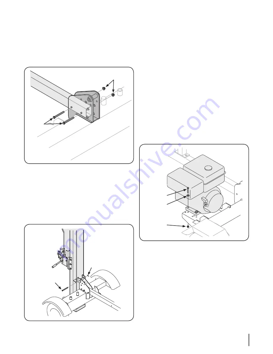
Place the tongue in position and secure with hardware just
removed. See Figure 3-5.
Lock Nuts
Hex Bolts
Figure 3-5
3.
Remove the reservoir tank from the blocks.
Attaching Beam To Reservoir Tank
1.
Stand the wedge, beam, and cylinder assembly upright
with cylinder toward the top.
NOTE:
This step will require two people.
2.
Remove the hinge pin and cotter pin from the welded
brackets on the beam assembly and move the reservoir
tank assembly in position against the beam. See Figure 3-6.
Hinge Pin
Cotter Pin
Figure 3-6
3.
Lift up on the tongue assembly until the holes are aligned
and insert the hinge pin just removed through brackets on
beam and reservoir tank assembly. See Figure 3-6.
4.
Secure the hinge pin with the cotter pin by bending the
ends of the pin. See Figure 3-6.
5.
Secure the beam to the tank by pulling out on the vertical
beam lock and rotating it up and over the edge of the
beam.
Attaching Engine-Pump Assembly
NOTE:
The Engine is secured to the crate by a pair of wood screw.
Remove these before beginning the assembly.
1.
Remove the engine mounting hardware from the engine
plate on the tank.
2.
Place the engine and pump assembly in position on the
engine mounting bracket with the pump facing towards
the jack stand.
3.
Align the holes in the base of the engine with the
appropriate holes in the engine mounting bracket.
4.
Secure the engine and pump assembly with the four hex
bolts, bell washers and lock nuts removed earlier. Using a
torque wrench, tighten to 14 ft-lbs. See Figure 3-7.
Hex Bolt
Bell Washer
Lock Nut
Figure 3-7
Summary of Contents for RM 33 LS
Page 22: ...Notes 10 22...
Page 23: ...23 Section 10 Notes...


