Distributor of Microchip Technology: Excellent Integrated System Limited
Datasheet of RN-ISP - PROGRAMMER ISP INTERFACE
Contact us: sales@integrated-circuit.com Website: www.integrated-circuit.com
www.rovingnetworks.com
3
RN -ISP-U M- 1.1
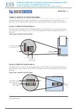
CONNECTING THE RN-ISP TO THE DEVELOPMENT PC & RN-IDK
Connect the components of the RN-IDK using the following steps:
1.
Connect the USB cable from the RN-ISP to the development PC.
2.
Connect the ISP 16-way ribbon cable from the RN-ISP to the RN-IDK’s H1 connector.
To install the RN-ISP, follow the instructions in EPSILON-6, EPSILON-1. Also refer to Known Issues (KNOWN-24) for
additional information.
Figure 1 shows the connection setup. The RN-ISP provides power to the RN-IDK.
Figure 1. RN-ISP Connected to the Development PC
USB Cable
RN-ISP Power LED
RN-ISP 16-Pin
Debug Header
RN-ISP
RN-IDK 16-Pin
Debug Header
RN-IDK Board
Computer’s USB Port
4 / 21
4 / 21


