ROWAN ELETTRONICA S.R.L. - Via Ugo Foscolo, 20 - 36030 CALDOGNO (VICENZA) ITALY
14
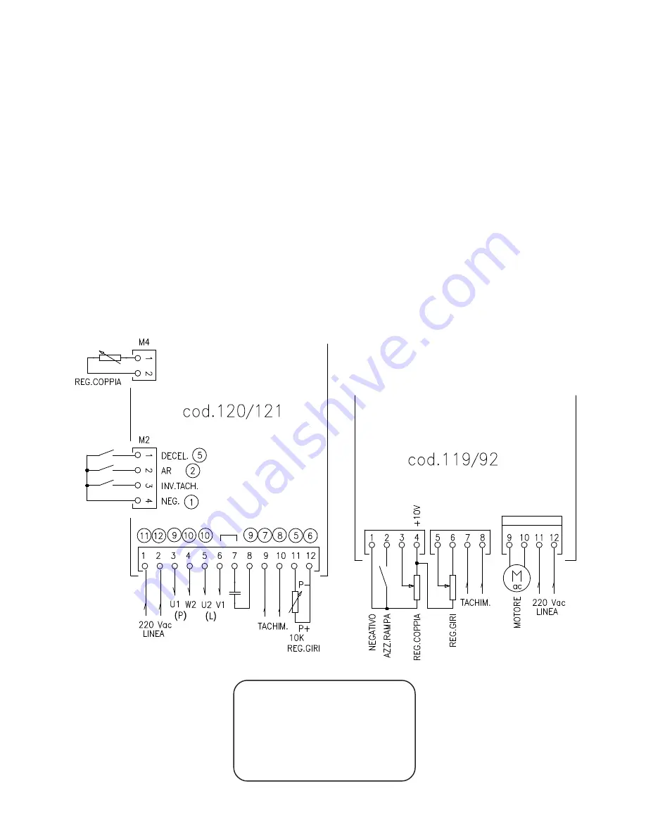
For the power connections proceed as follows:
the wires that were connected to the terminals 1 and 2 are to be shifted to terminals 11 and 12 of C119/92, whereas
the wires connected to terminals 3 4 5 6 7 8 related to the capacitor and power and launching windings are to be
reconnected together as shown in the schematic.
For the control connections proceed as follows:
the tachometer wires that were connected to terminals 9 and 10 are to be connected to terminals 7 and 8 of C119/92,
whereas the potentiometer wires as follows: P-(OV), connected to terminal 11, must be shifted to terminal 6,
whereas P+, connected to terminal 12, must be shifted to terminal 5 of C119/92.
For control wires connected to lateral terminal strip M2 of board C120/121 proceed as follows:
shift the wire connected to terminal NEG to terminal 1 of C119/92;
shift the wire connected to terminal AR to terminal 2 of C119/92;
exclude the wire connected to terminal INV. TACH. since it is unnecessary for C119/92;
connect wire connected to terminal DECEL to terminal 5 of C119/92.
Close microswitch S1 (for other microswitches refer to the paragraph describing the microswitches).
If a potentiometer is connected to terminal board M4 for torque limitation, you should reconnect it to terminals
1 3 4 of code 119/92 with 3 wires as illustrated in the schematic diagram; in this case close microswitch S2.
The circled numbers in the schematic refer to the terminals on C119/92.
Reg. Coppia = Torque Regulation
Reg. Giri = Speed Regulation
Tachim.= Tachometer Generator
Linea = Mains Line
Negativo = Negative
Azz. Rampa = Ramp to zero setting
Inv. Tach. = Tachometer Inversion
Decel = Deceleration
Replacing drive C120/121 with drive C119/92


