ROWAN ELETTRONICA s.r.l. - Via Ugo foscolo, 20 - 36030 CALDOGNO (Vicenza)
page 10 out of 24
INSTRUCTIONS FOR CORRECT INSTALLATION
MECHANICAL INSTALLATION
Install the drive keeping in mind the following points:
-Verify that the characteristics of the place where the drive is to be placed is within the environmental characteristics given on
page 3 (temperature-humidity-protection grade).
- Favour a cooling airflow as much as possible. Do not place the drives one above the other. Leave a space of at least 100
mm above and below the drive, and one of at least 50 mm on both sides.
- Avoid vibrations and excessive impacts.
- Leave enough space for the possible installation of anti EMI filters (see following paragraph).
The code 390S card works correctly when the container temperature and the temperature inside its housing panel is
between –5°C and +55°C. Higher or lower temperatures could incite operational irregularities or drifts in speed control
and breakage if the temperature is very high. It is therefore advisable to position the cards far from heat sources and
ventilate the panel when the environmental temperature is high.
ELECTRICAL PROTECTIONS
The code 390S card is equipped with a protecting device which intervenes when the motor is out of tachometric control i.e. in
cases of overload, lack of line and motor phase, in the absence of a tachometrical dynamo and inverted tachometric polarity
if the internal precision rectifying device is not being used. The emergency intervention does not let the motor rotate and
commands the emergency relay connected externally. The card controlling circuit is also protected by a triad of 0.5A fuses
housed in the lower card which carries the power terminal board. It is necessary to install power amperometric connections
in the form of external 20A fuses for short circuits of the GL RAPIDI type, and a relay calculated for a current which is 15%
higher than the nominal one.
As an alternative to the thermal relay, a circuit breaker sensor could be incorporated into the motor.
Use relays with low current contacts for the running and stop in ramp commands or to select potentiometers or DC signals.
Avoid using the auxiliary contacts of the electromagnetic switches for this type of operation, but if this is necessary wind the
contacts together.
CABLING SYSTEM AND ELECTROMAGNETIC COMPATIBILITY
In order to limit disturbances induced in the connecting cables as much as possible:
-
Avoid passing the control terminal board connecting cables in the same channel as the power connecting cables
-
Connect potentiometers, tachometrical dynamo and DC signals with screened cable
-
Connect an end of each card singularly to the common earth point of the panel.
-
Avoid earth loops.
-
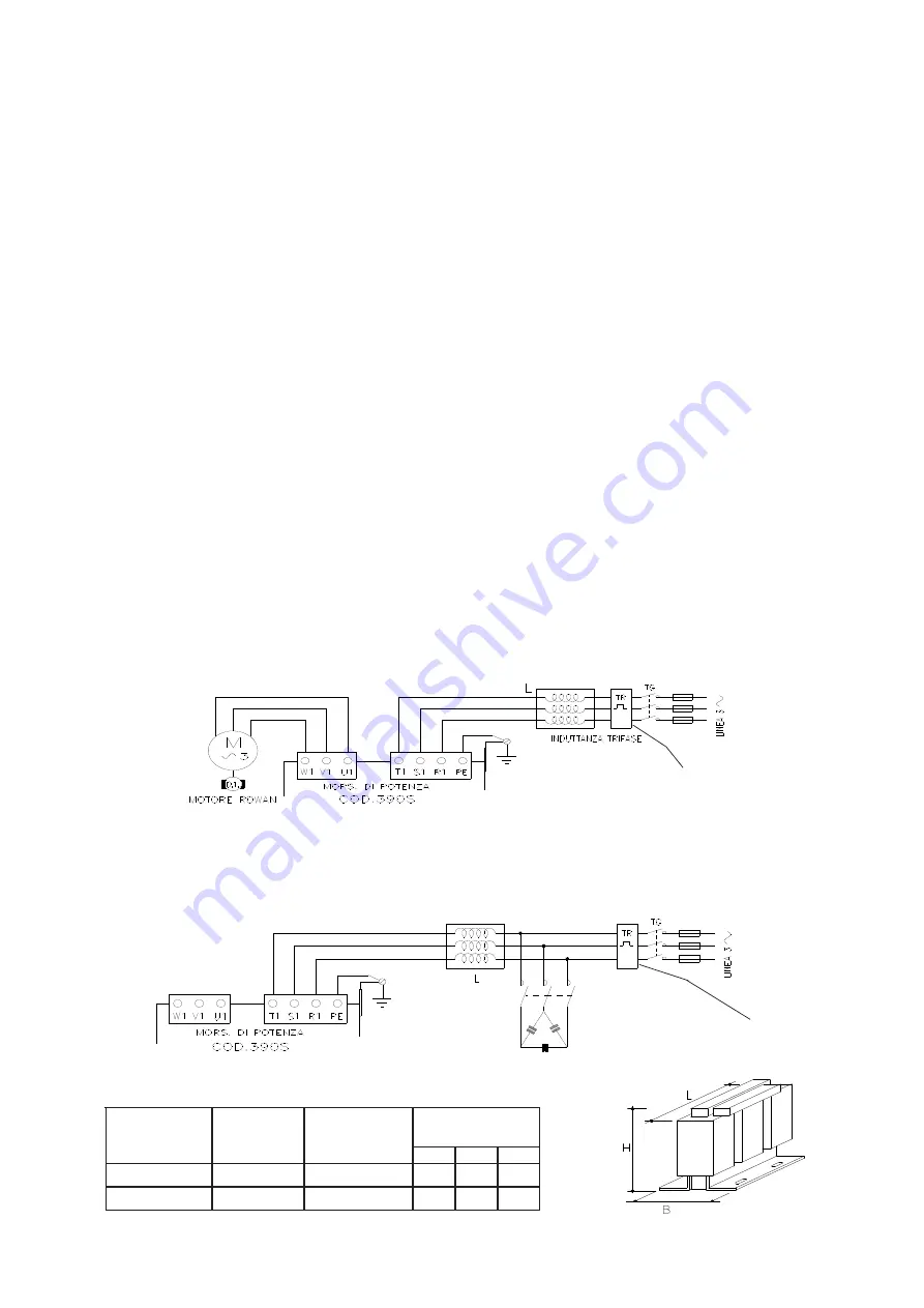
To limit emissions conducted on the supply line and to better immunity towards disturbances of the same type, connect
the filter inducer and connect the terminals indicated and to the common earth point.
Warning! The anti EMI filter works with a small current dispersion towards earth which, at the moment of supply, could cause
very sensitive differentials to intervene. It is advisable, therefore, to use differentials for variable currents.
Upon request Rowan Elettronica can supply the complete ANTI EMI filter: the inductors are chosen according to the nominal
current of the applied Rowan motor, or to the total of several motors. A single inductor can serve several drives in parallel.
If a power factor improvement circuit is to be applied, it must be inserted upstream of the ANTI EMI filter, but the emission
reduction effect will be eliminated. Inserting power factor improvement capacitors also further reduces EMI emissions.
CODES AND CHARACTERISTICS OF THE ANTI E.M.I. THREEPHASE INDUCTORS
E
D
O
C
M
U
M
I
X
A
M
T
N
E
R
R
U
C
( )
A
E
C
N
A
D
E
P
M
I
(
)
H
m
)
m
m
(
S
N
O
I
S
N
E
M
I
D
H
B
L
5
,
1
.
A
0
1
.
T
P
M
I
0
1
5
.
1
5
2
1
5
6
0
2
1
9
0
.
A
0
2
.
T
P
M
I
0
2
9
.
0
0
5
1
5
7
0
5
1
FOR MOTORS MEC 63 ONLY
FOR MOTORS MEC 63 ONLY
RE-PHASING CAPACITOR
SPECIAL SWITCH
for CAPACITORS
I N S E R T I O N
Telemecanique LC1
DFK11 type


