ROWAN ELETTRONICA s.r.l. - Via Ugo foscolo, 20 - 36030 CALDOGNO (Vicenza)
page 14 out of 24
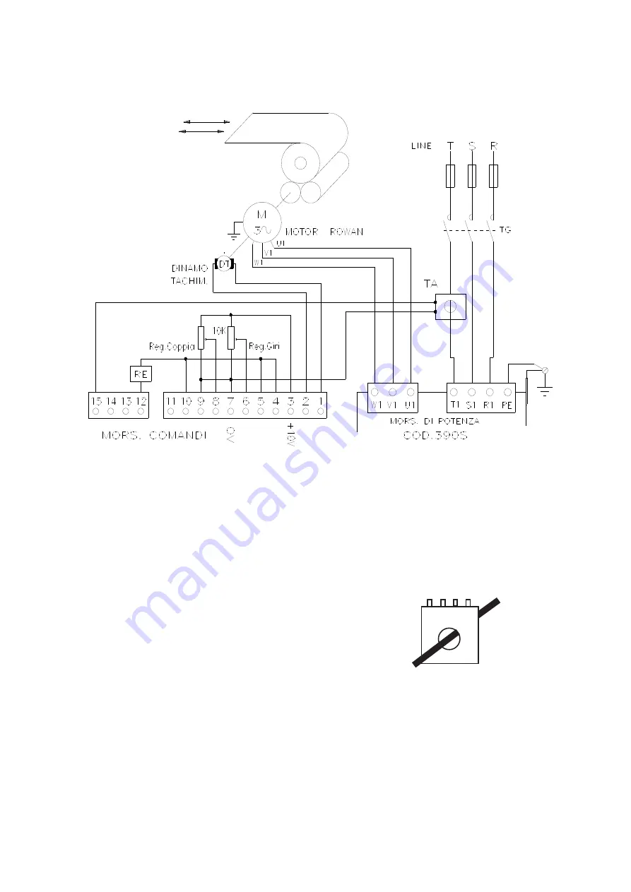
Connection diagram nr. 2
SPEED / COUPLE CONTROL WITH AMPEROMETRIC FEEDBACK
The diagram shows a usage example of this type of operation, i.e. a Rowan motor that tangentially drags a roll to be
wound or unwound using adjustable pull.
The maximum speed is established by the turn adjustment potentiometer while the maximum pull is established by the
couple adjusting potentiometer, which limits the current of the controlling motor in closed loop with the amperometric
transformer (TA). The maximum field of the couple regulating potentiometer can be set using both the P9 MAXIMUM
COUPLE trimmer and the way in which the TA is used (outlet connected and number of wire passages).
The card is set to operate with an amperometric transformer of the 151/110 type, with full scale 4VAC/0.2A supplied by
Rowan Elettronica. TA characteristics 151/110 with ONE WIRE PASSAGE:
Outlet 1-2 = maximum output 25A
Outlet 1-3 = maximum output 50A
Outlet 1-4 = maximum output 100A
Note: the tachometric rectifier should be excluded (S4 closed – S5 open).
The maximum capacity of the various outlets can be divided by the number of wire passages: for example if the 1-2 outlet
is used and 5 wire passages are carried out inside the TA the maximum output will be for a current of 5A: choose the TA
outlets and the wire passages according to the nominal current of the Rowan motor applied.
This operation can be integrated by automatic systems with external apparatus of the PLC type, or a Rowan code 274
servodiameter instrument (as in the case of winder/unwinder with adjustable pull and motor in axis to the roll). With a 0
/ +10VDC signal, this apparatus can supply the maximum speed signal to terminals 13-14 (0V) and the maximum couple
signal to terminals 11 – 7 (0V), in place of manual adjustment with potentiometers.
WARNING: keep in mind that while operating with blocked rotor the maximum current of the Rowan motor in continuous
duty must be at least 20% lower than the nominal current.
Connection diagram nr. 3
1 2 3 4
MOTORIZED COIL IN TANGENCY


