background image

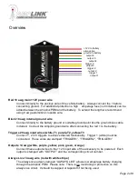
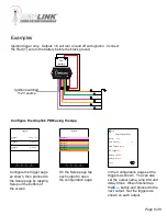
Red 10 awg main +12V power wire


Connect directly to the positive pole of the vehicle battery.  Always connect the + before 
connecting ground.  For additional protection a high 

amperage fuse (not included) can be 

added between the Amplink PDM and the battery.  To extend the length we recommend 
using 8 awg automotive crosslink wire.  

Black 18 awg internal ground wire

Connect directly to the battery ground or suitable ground point like the ground buss cable 
included.  Connect the Amplink ground wire after connecting the red + to the battery.

Triggers 20 awg input wires (white-T1, purple-T2, yellow-T3

Connect 1, 2 or 3 triggers to achieve desired functionality.  Trigger 1 (white) must be         

           connected.  

These wires are stamped “TRIGGER1”, “TRIGGER2”, “TRIGGER3”

Outputs 14 awg (white, purple, yellow, pink, green, orange)

Connect these output wires to the +12V input wire of the accessory to be powered.  Each 
output is stamped with “OUTPUT” and the corresponding circuit number.

Always Live 14 awg wire (red with white stripe)

The always live output, 

stamped “ALWAYS LIVE” allows low amperage battery charging 

through the Amplink PDM.  Please note:  There is no monitoring or protection on this 
always live circuit.  It should be capped or taped off if not being used.

+12V to battery

ground to battery

trigger 1

trigger 2

trigger 3

output 1

output 2

output 4

always live

output 6

output 5

output 3

Overview

Page 2 of 8

Summary of Contents for Amplink PDM

Page 1: ...2 x 50 8 x 22 9 mm Package Contents 1 Amplink Power Distribution Module 1 Ground bus kit with cover 6 ring terminal for use on accessory ground wires connected to the ground bus 1 6MM bolt nut used fo...

Page 2: ...T3 Connect 1 2 or 3 triggers to achieve desired functionality Trigger 1 white must be connected These wires are stamped TRIGGER1 TRIGGER2 TRIGGER3 Outputs 14 awg white purple yellow pink green orange...

Page 3: ...od Note Before completing a full installation of your Amplink we recommend bench testing to ensure your setup functions as desired Amplink PDM App Page 3 of 8 The app is designed to be simple and stra...

Page 4: ...dicated by the green LED 2 If this is your first time connecting a Bluetooth device to the Amplink PDM proceed to step 3 or skip to step 9 if you ve already setup your device to pair with the Amplink...

Page 5: ...ettings including output name amperage limit delay on delay off trigger logic and or Tap the output name to open the output configuration screen Tapping Back will save and exit the configuration scree...

Page 6: ...er 3 Off Trigger 2 Off Voltage ve Disabled Disabled Outputs Output 1 Output 2 Output 3 Output 4 Output 5 Output 6 Monitor Setup Triggers Information Configure the trigger page as shown then proceed to...

Page 7: ...the Setup page by tapping Setup on the bottom of the screen Monitor Setup Triggers Information On the Setup page tap each output to open the configuration page In the Configuration page for output 1...

Page 8: ...or warranty claims This warranty covers parts and our labor for those parts to be replaced or repaired at a service facility we designate Please contact your dealer or Rowe Electronics Inc Specific di...

Reviews: