
Horn
button
Horn
Trigger 2
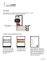
Examples
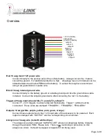
Ignition triggered outputs and Horn output. Outputs 2-6 will turn on and off with ignition,
Output 1 will turn on when the ignition is on and the horn button is pressed.
Back
Output Configuration
OR Triggers
None
AND Triggers
T1, T2
Delay On 00:00
Amp Limit (A)
Name
Horn
Delay Off 00:00
Test
20
Triggers
Trigger 1
On
Trigger 3
Off
Trigger 2
Off
Voltage (+ve)
Voltage (+ve)
Disabled
Outputs
Output 1
Output 2
Output 3
Output 4
Output 5
Output 6
Monitor
Setup
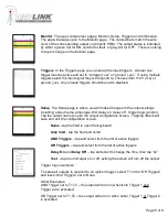
Triggers Information
Configure the trigger
page as shown, then
proceed to the Setup
page by tapping
Setup on the bottom
of the screen
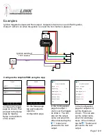
Monitor
Setup
Triggers Information
On the Setup page
tap each output to
open the
configuration page.
In the Configuration
page for output 1
(horn), set the triggers
as shown. You can
also set the output
name and amp limit.
When finished tap the
button and
proceed to the next
output.
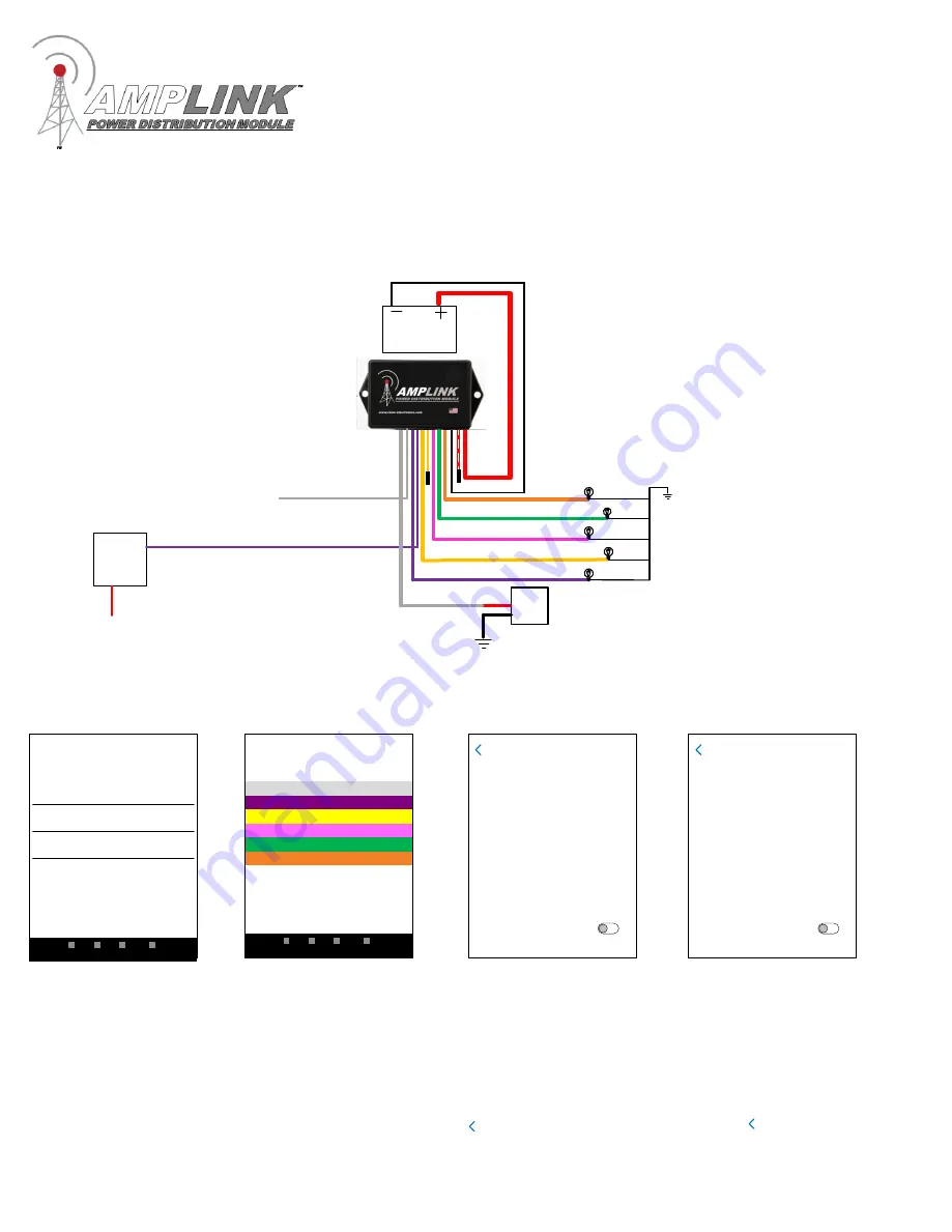
Back
Back
Output Configuration
OR Triggers
T1
AND Triggers
None
Delay On
00:00
Amp Limit (A)
Name Output 2
Delay Off
00:00
Test
5
In the Configuration
page for outputs 2-6,
set the triggers as
shown. You can also
set the output name,
amp limit and delay
times. When finished
tap the button and
proceed to the next
output.
Back
Configure the Amplink PDM using the App
Page 7 of 8
12V
battery
Ignition switched
+12V source
+12V


