DLW-1 Phonograph
10-26
21822662
ADDING MICROPHONES
STUDIO SOUND ONLY
Do not skip steps. All steps must be done to navigate properly through the menus.
If you get lost, back through the menus by
touching: BACK, the BACK arrow, or Back to Peripheral Setup.
Up to three microphones can be plugged into the Audio/Video Controller and used for paging. Microphones can be Rowe, low-
level balanced, or low-level unbalanced. All microphones must have a momentary PUSH to TALK switch (see Figure xxx).
Step 1.
Check microphone muting, Mic type, and VCU settings:
•
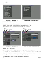
Push SERVICE SWITCH to enter Main Menu.
• Touch
Hardware/Diagnostics.
• Touch
Configure Hardware.
• Touch
Audio Modes to view Audio Modes, Input Select screen.
• Touch
Muting to view Audio Modes, Muting screen.
•
In the Microphone row, remove any check marks by
touching
them.
• Touch
BACK arrow to return to Hardware Setup.
• Touch
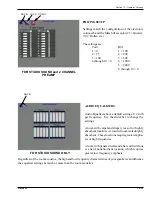
Microphone Setup to view Microphone Setup, Setup screen.
•
The paging column should have all red dots.
Touch
any blue to make it red.
• Touch
BACK arrow to return to Hardware Setup.
• Touch
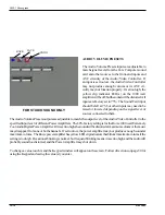
Remote Control Setup to view Remote Control, Parameters screen.
• Touch
VCU Settings to view Remote Control, VCU Settings screen.
•
In the VCU1 row,
touch
the microphones you are adding, that do not have a check mark.
• Touch
SAVE arrow to record your changes
Step 2.
Plug in the microphone(s). If you are adding only low-level microphones, go to Step 3. Rowe microphones
have a built-in volume control, but are also affected by the microphone volume settings of the phonograph Volume
Control Unit. Set the volume control on each Rowe microphone you are adding to maximum, and do a test page
with them. Remove any distortion by lowering the corresponding microphone volume on the phonograph Volume
Control Unit. Then do the following to disable those microphone keys on the VCU.
• Touch
Parameters to view Remote Control, Parameters screen.
• Touch
VCU Settings to view Remote Control, VCU Settings screen.
•
In the VCU1 row, remove check marks corresponding to Rowe microphones by
touching
them.
• Touch
SAVE arrow to record your changes
Step 3.
Use the phonographs’ Volume Control Unit to control the volume of the low-level microphones. Do a test
page with each low-level microphone.
Step 4.
During paging, the music level drops to whichever is greater: 6 db or the override settings. Each channel
has its own override setting in the range of 0 to 63, and channels 1, 2, 3, and 4 are factory set to 33. Set to 63 if
you want minimum reduction of the music. To change the override settings:
• Touch
BACK arrow to return to Hardware Setup.
• Touch
Microphone Setup to show Microphone Setup, Setup screen.
•
For each override setting.
• Touch
box showing override value.
• Touch
C to clear the present value, enter the new value, and
touch
OK.
• Touch
SAVE arrow to record your changes
Step 5.
Each microphone can be routed to any combination of the six output channels: 1, 2, 3, 4, AuxL, and AuxR.
The factory setting route all 3 microphones to all six output channels. To change the routing:
• Touch
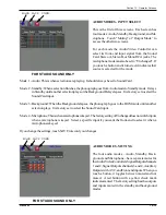
Routing to show Microphone Setup, Routing screen.
•
Set the routing for each microphone. When you
touch
a button, it toggles between routed and not routed. A red
button with a yellow check mark indicates routed.
• Touch
SAVE arrow to record your changes.
• Touch
BACK arrow to return to Hardware Setup.
Summary of Contents for StarLink DLW-1
Page 8: ......
Page 22: ...DLW 1Phonograph 1 12 21822662 This page left intentionally blank...
Page 37: ...Section 3 Venue Installation 21822662 3 11 THIS PAGE INTENTIONALLY LEFT BLANK...
Page 39: ...Section 3 Venue Installation 21822662 3 13 THIS PAGE INTENTIONALLY LEFT BLANK...
Page 50: ...DLW 1Phonograph 4 4 21822662 This page intentionally left blank...
Page 72: ...DLW 1 Phonograph 5 22 21822662 This page intentionally left blank...
Page 90: ...DLW 1Phonograph 8 8 21822662 This page intentionally left blank...
Page 96: ...DLW 1 Phonograph 9 6 This Page Intentionally Left Blank...
Page 120: ...DLW 1 Phonograph 10 24 21822662 SPANISHUSERINTERFACE...
Page 128: ...DLW 1 Phonograph 10 32 21822662 This page left intentionally blank...
Page 130: ...11 2 21822662 This page intentionally left blank...
Page 139: ...11 11 21822662 This page intentionally left blank...
Page 141: ...11 13 21822662 7 8 Figure 11 3A Shell Assembly Internal View 1000 Watt 2 Channel Preamp...
Page 145: ...11 17 21822662 This page intentionally left blank...

