Section 2: Installing Hard Drive and Testing
21822662
2-3
TESTING THE UNIT
Once the jukebox is powered on and the user interface is running (see figure 2-5 Jukebox User Interface), try the
following procedures before moving and installing the unit at the venue:
PERIPHERALS
Touch Screen:
NOTE:
Every time a hard drive is installed in a CC enclosure, the touch screenneeds to be calibrated.
The following procedure describes how to calibrate the touch screen:
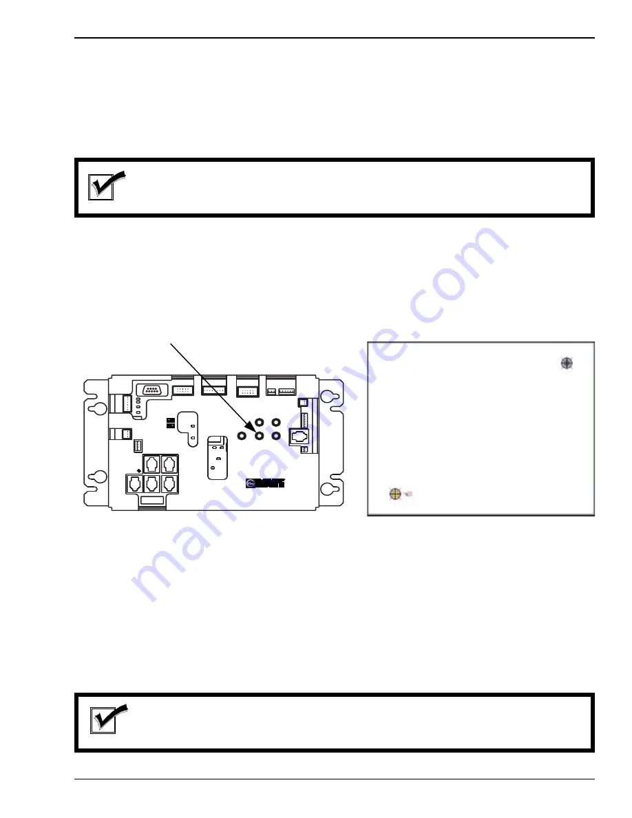
1. Press the “Calibration” button on the Rowelink Controller (see figure 2-3). Press the button in once to
launch the calibration program. This will override the application while the program runs. See figure 2-4
for a picture of the calibration program interface.
2. Close the phonograph door and make sure it is locked.
3. Follow the directions on the screen, touching the center of the target, then touching YES.
Bill Acceptor:
Insert a dollar bill in the jukebox and check that the increment in credits available corresponds with the pricing
scheme for the jukebox.
Credit Card Reader:
Fully insert and remove any magnetic card (credit, debit, or Club Ecast) into the dipper while the application is
running, and assure that the card is acknowledged by the application. The card will not be charged if the jukebox
is not hooked up to a network or if the process is cancelled before a dollar amount is selected.
NOTE:
The credit card reader only accepts Visa and Master card at this time. A nonaccepted card will
return a dialogue box to the user to try a different card.
FIGURE 2-4
CALIBRATION SCREEN
FIGURE 2-3
ROWELINK CONTROLLER
TB1
ROWELINK
P6
P7
P9
P5
P8
P10
POWER OUT
P23
P14
POWER IN
POWER IN
12 VDC
24 VDC
24 VAC
5 VDC
RS232
P22
CC RL RX
CC RL TX
P21
COIN
ACCEPTOR
P20
COIN
SWITCHES
P19
BILL
ACCEPTOR
POWER
CALIBRATE
SERVICE
REJECT
COLLECT
R
ROWELINK CONTROLLER
40926001
P3
AMP MUTE
P11
IR DETECTOR
P12
SW'S
P17
P18
COUNTER
MDB
BILL
ACC.
POWER
P16
CRDT STATUS
KID RL TX
CRDT RL TX
IR RCV
1000 W
250 W
P15
REJECT
CALIBRATION
BUTTON
Summary of Contents for StarLink DLW-1
Page 8: ......
Page 22: ...DLW 1Phonograph 1 12 21822662 This page left intentionally blank...
Page 37: ...Section 3 Venue Installation 21822662 3 11 THIS PAGE INTENTIONALLY LEFT BLANK...
Page 39: ...Section 3 Venue Installation 21822662 3 13 THIS PAGE INTENTIONALLY LEFT BLANK...
Page 50: ...DLW 1Phonograph 4 4 21822662 This page intentionally left blank...
Page 72: ...DLW 1 Phonograph 5 22 21822662 This page intentionally left blank...
Page 90: ...DLW 1Phonograph 8 8 21822662 This page intentionally left blank...
Page 96: ...DLW 1 Phonograph 9 6 This Page Intentionally Left Blank...
Page 120: ...DLW 1 Phonograph 10 24 21822662 SPANISHUSERINTERFACE...
Page 128: ...DLW 1 Phonograph 10 32 21822662 This page left intentionally blank...
Page 130: ...11 2 21822662 This page intentionally left blank...
Page 139: ...11 11 21822662 This page intentionally left blank...
Page 141: ...11 13 21822662 7 8 Figure 11 3A Shell Assembly Internal View 1000 Watt 2 Channel Preamp...
Page 145: ...11 17 21822662 This page intentionally left blank...


