28/36
GB
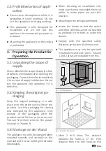
floor must be at least 1.85 m in order
to keep a minimum distance of 1.50 m
from the appliance to the floor).
2. Drill the holes previously marked with
a diameter of Ø 6 mm and a depth of
approx. 55 mm.
3. First place the dowels provided in the
drill holes. Then screw in the screws
provided – making sure that the screw
head still protrudes about 8 mm.
Fig.3: Drill holes
4. Now hang up the appliance carefully at
the two screws.
5. The lower fastening (see Fig. 4) must
be attached for a secure hold. Turn this
downwards for the purpose. Draw a
marking through the hole onto the wall.
Mounting
bracket
Lower
fastening
Fig.4: Attachment
6. Unhang the appliance again and drill at
the marking with a diameter of Ø 6 mm
and a depth of approx. 55 mm into the
drill hole previously marked.
7. Now hang the appliance back on the
mounting bracket and fix it on the
lower fastening with a screw.
4. Operating Instructions
4.1 Appliance overview
1
2
3
1
2
3
Display
Air grating
Control unit
Fig. 5a: Appliance overview
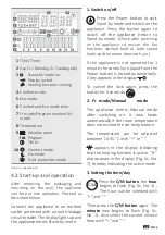
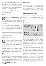
C/M
P/PRO
+
POWER
“+”
BUTTON
“-”
BUTTON
SETTING THE
DAY, TIME AND
TIMER
SETTING THE
HEATING
PROGRAM
UNLOCK/
WINDOW OPEN
Fig. 5b: Control unit


