29/40
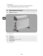
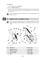
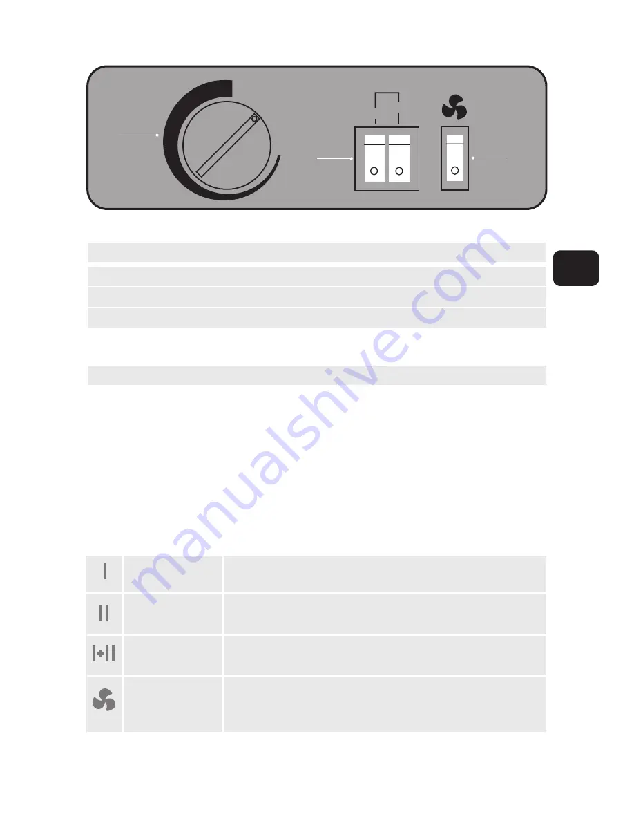
Fig. 2: Control unit
No. Designation
1
Blower function
(depending on model)
2
Heating level switch
3
Temperature control (thermostat)
Tab. 3: Control unit
3.2
Start-up and operation
After removing the packaging and assembly, the appliance can be put into operation.
Proceed as follows for this:
1. Make sure the heating level switches (see Fig. 2, No. 2) are pressed down, in the OFF
position and the pilot lamp is off. Then connect the heat convector to an earthed socket
protected with an earth-leakage circuit breaker.
2. Now switch on the appliance by moving the heating level switch (see Fig. 2, No. 2) to
the desired heat output. The following options are available for selection:
Tab. 4: Switch levels
MIN
MAX
750 W
1250 W
2000 W
1
3
2
Heating level 1
Heating level 2
Heating level 3
Blower function*
If the heating level switch is in this position,
the heat convector will provide a heat output of 750 W.
If the heating level switch is in this position,
the heat convector will provide a heat output of 1250 W.
If the heating level switches are in this position,
the heat convector will provide a heat output of 2000 W.
Press the rocker switch to position "I" to activate the blower
function.
(* Not available for HWK 2000/3/2 Basic)
GB


