background image

22

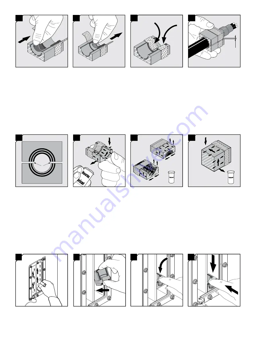
Insert the modules at an angle 
from the backside of the transit 
according to your installation 
plan.

23

Turn the modules in line with the 
frame.

24

Push the modules in place. 
Ensure that the module rests 
against the stopping edge at the 
front.

A

16

Achieve a gap of 0.1-1.0 mm (A) 
between the module halves by 
peeling off layers. The cable 
armor shall be in contact with the 
braid.

TM

13

Adapt the layers that are in 
contact with the cable jacket.

15

Fold the braid tightly inside the 
module half.

18

Lubricate the sealing surfaces 
of all modules with Roxtec 
Lubricant. Avoid excess lubricant 
on the braid.

19

Lubricate the sealing surfaces 
of the spare modules. Do not 
remove the core.

BG B

BG B

TM

14

Adapt the layers that are in 
contact with the cable armor.

A

The number of layers may not 
differ (A) by more than one 
between the corresponding 
module halves.

17

20

Lubricate the sealing surfaces of 
the solid modules.

21

Lubricate the inside surfaces of 

the frame all around, especially 

into the corners. Lubricate the 

area that will be in contact with 

the braid sparsely.

Summary of Contents for CM BG B Series

Page 1: ...allation codes Any action affecting the routed service should be performed according to manufacturer recommendations Module size For cable outer diameter min max CM 20 BG B 4 14 5 CM 20w40 BG B 3 5 16 5 CM 30w40 BG B 10 25 CM 40 10 32 BG B 9 5 32 5 CM 40 BG B 21 5 34 5 Roxtec CM BG B modules Measures in millimeters mm Roxtec CM BG B solid modules Module size CM 10w40 0 BG B CM 20 0 BG B CM 40 0 BG...

Page 2: ...spanner not included Cable stripper tool Recommended by the cable manufacturer not included Continuity tester not included Roxtec installation tools not included Tools Packing space As module installation example shows 160 mm can be the result of 3 pieces of CM 40 10 32 BG B and 2 pieces of CM 20w40 BG B Different module configurations must be totally 160 mm CM 20w40 BG B 20 CM 20w40 BG B 20 CM 40...

Page 3: ...nter frames from the inside of the cabinet 7 Tighten the nuts crosswise in small steps Recommended torque 4 Nm Do not overtighten the nuts 8 All BG frames must be clean and have electrical contact with protective earth National regulations apply 11 Correct placement of a cable in a CM BG B module The cable armor shall be visible outside the module 12 Remove the core and fold out the braid 9 Remove...

Page 4: ...e cable jacket 15 Fold the braid tightly inside the module half 18 Lubricate the sealing surfaces of all modules with Roxtec Lubricant Avoid excess lubricant on the braid 19 Lubricate the sealing surfaces of the spare modules Do not remove the core BG B BG B TM 14 Adapt the layers that are in contact with the cable armor A The number of layers may not differ A by more than one between the correspo...

Page 5: ...n the first compression unit until the second compression unit is inserted 35 The compression units can be placed with the screwhead facing the inside B or the outside A of the frame A B 36 26 When placing cables in modules the cable armor shall be visible outside the module at the termination side 27 Place cables according to your packing plan in the module halves Place corresponding module halve...

Page 6: ...nd fully inserted after compression 39 If applicable check that the protective bonding conductor is correctly installed 40 Verify earth continuity from each cable armor to the earthing terminal using a suitable instrument 37 Tighten the screws of the compression units alternately until full stop approx 20 Nm ...

Page 7: ...rom the backside of the frame Do not damage the braids 3 Lift up the stayplate and push out the first module from the front side 4 Remove the stayplate 2 Remove the compression units 6 The inside surfaces of the exposed packing space shall be clean and conductive 7 Lubricate the inside surfaces especially in the corners Continue the reinstallation ...

Page 8: ...thorized manufacturer Roxtec gives no perfor mance guarantee with respect to the Roxtec system unless I all components installed as part of the Roxtec system are manufactured by an authorized manufacturer and II the purchaser is in compliance with a and b below a During storage the Roxtec system or part thereof shall be kept indoors in its original packaging at room temperature b Installation shal...

Reviews: