PRINCIPLE OF OPERATION
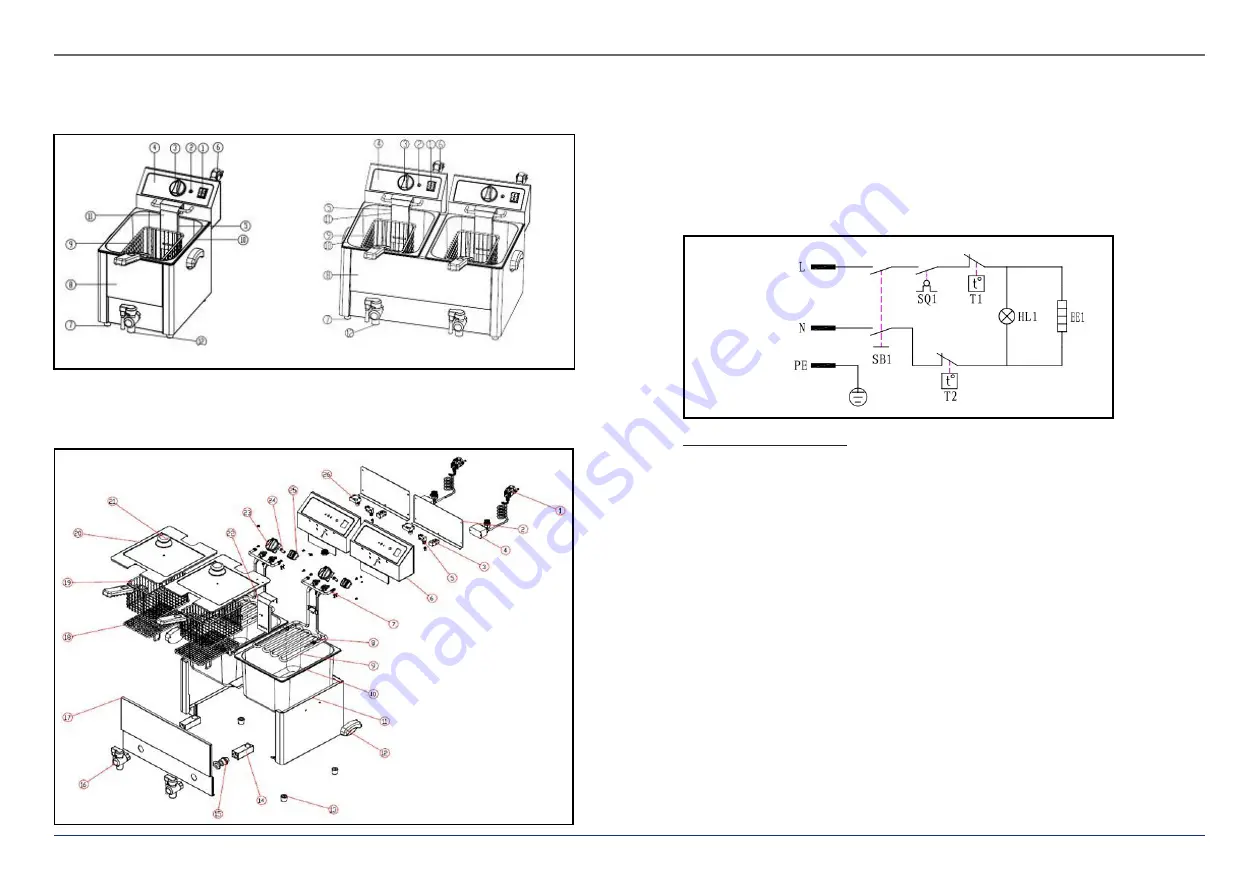
Assembly
1. ON-OFF-Switch 2. Control Light 3. Thermostat Knob 4. Electric Box 5. Heating Element 6. Power Cable
7. Rubber Foot 8. Housing 9. Frying Basket 10. Tank 11. Protection Board 12. Drain Valve
EN
EN
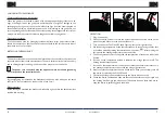
Solid Diagram
1. Power Cable 2. Cover of the Electric Box 3. Connector 4. Relay 5. Microswitch 6. Electric Box
7. Hanging 8. Temperature Sensor 9. Heating Element 10. Tank 11. Housing 12. Plastic Handle
13. Rubber Foot 14. Square Tube 15. Connector lug 16. Drain Valve 17. Front Plate 19. Frying Basket
20. Cover 21. Handle of the Cover 22. Protection 23. Thermostat Knob 24. Control Light
25. ON/OFF-Switch 26. Temperature limiter
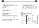
Wiring Diagram
230 V / 50 Hz
The device is composed of:
1. An ON/OFF switch,
2. A thermostat to regulate the temperature at the level wished,
3. A control light (orange for the heating),
4. A heating element in the lower part of the device, which is controlled by the
thermostat.
FUNCTIONING
The temperature measurement in the tank is made at regular intervals. This information
is transmitted to the thermostat as a current value, and gets compared to the value
set by the user.
•
If the current value is inferior to the set value, the thermostat makes the device
heat.
•
If the current value is superior or equal to the set value, the thermostat stops the
heating.
4
Rev. 02.03.2021
5
Rev. 02.03.2021


