3-1-20
2A3/4
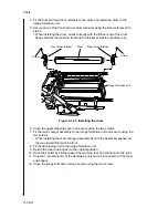
4. Fit the front and rear drum retainers to the drum and install the drum to the
image formation unit.
5. Secure each of the front and rear drum retainers using the screws removed in
step 3.
• When installing the drum, orient correctly with the thinner end of the drum
flange shaft at the machine front and the thicker end at the machine rear.
Image formation unit
Screw
Screw
Front drum retainer
Drum
Rear drum retainer
Figure 3-1-24 Installing the drum
6. Close the upper cleaning cover and secure using the two screws.
7. Fit the main charger assembly to the image formation unit and secure using the
two screws.
• When installing the main charger assembly, fix with the assembly pushed all
the way toward the machine front.
8. Fit the developing unit to the image formation unit.
9. Return the toner sub-hopper to the original position.
10. Open the shutter by sliding toward the machine rear and connect it to the joint.
11. Plug the 1-pin connector of the developing unit and 4-pin connector of the toner
sub-hopper.
12. Close the image formation rail and secure using the two screws.
Summary of Contents for Ri 4230
Page 3: ...SERVICE MANUAL Ri 4230 5230 ...
Page 13: ...4230 5230 S M MCA THEORY AND CONSTRUCTION SECTION I I Theory and Construction Section ...
Page 14: ...1 1 5 2A3 4 CONTENTS 1 1 Specifications 1 1 1 Specifications 1 1 1 ...
Page 100: ...4230 5230 S M MCA ELECTRICAL SECTION II II Electrical Section ...
Page 119: ......
Page 138: ......
Page 159: ...4230 5230 S M MCA III Set Up and Adjustment Section III SET UP AND ADJUSTMENT SECTION ...
Page 448: ...2A3 4 3 6 3 25 Toner scatters at the leading edge of the image See page 3 6 17 ...


