3-1-33
2A3/4
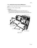
3-1-4 Installing the image memory SIMM (option)
Installation of add-on image memory to the memory copy PCB requires the following
part:
Image memory (16 MB or 32 MB 72-pin SIMM)
<Procedure>
1. Detach the SRDF connector.
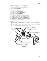
2. Remove the seven screws holding the rear cover and then the cover.
3. Remove the eight screws holding the main PCB cover and then the cover.
• To install an add-on image memory to memory copy PCB 2 only, proceed to step
5.
Memory copy PCB 2
Memory copy PCB 1
M4
Screws
Main PCB cover
Screws
Screws
Figure 3-1-41
Summary of Contents for Ri 4230
Page 3: ...SERVICE MANUAL Ri 4230 5230 ...
Page 13: ...4230 5230 S M MCA THEORY AND CONSTRUCTION SECTION I I Theory and Construction Section ...
Page 14: ...1 1 5 2A3 4 CONTENTS 1 1 Specifications 1 1 1 Specifications 1 1 1 ...
Page 100: ...4230 5230 S M MCA ELECTRICAL SECTION II II Electrical Section ...
Page 119: ......
Page 138: ......
Page 159: ...4230 5230 S M MCA III Set Up and Adjustment Section III SET UP AND ADJUSTMENT SECTION ...
Page 448: ...2A3 4 3 6 3 25 Toner scatters at the leading edge of the image See page 3 6 17 ...


