3-1-40
2A3/4
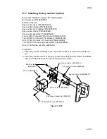
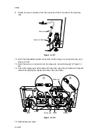
13. Remove the two screws holding the lower left cover and then the cover.
14. Remove the cap in the lower left cover.
15. Refit the lower left cover using the two screws.
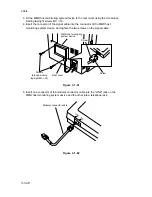
16. Insert the heater switch instead.
17. Plug the two 1-pin connectors of the dehumidifier relay cable onto the terminals of
the heater switch.
Heater switch
Heater switch
1-pin connector
Dehumidifier relay cable
1-pin connector
Cap
Figure 3-1-49
18. Refit all removed parts.
Summary of Contents for Ri 4230
Page 3: ...SERVICE MANUAL Ri 4230 5230 ...
Page 13: ...4230 5230 S M MCA THEORY AND CONSTRUCTION SECTION I I Theory and Construction Section ...
Page 14: ...1 1 5 2A3 4 CONTENTS 1 1 Specifications 1 1 1 Specifications 1 1 1 ...
Page 100: ...4230 5230 S M MCA ELECTRICAL SECTION II II Electrical Section ...
Page 119: ......
Page 138: ......
Page 159: ...4230 5230 S M MCA III Set Up and Adjustment Section III SET UP AND ADJUSTMENT SECTION ...
Page 448: ...2A3 4 3 6 3 25 Toner scatters at the leading edge of the image See page 3 6 17 ...


