2A3/4
3-3-24
( 2 ) Detaching and refitting the scanner wires
Take the following procedure when the scanner wires are broken or to be replaced.
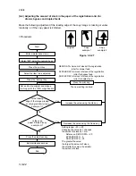
• After replacing the scanner wires, proceed to (5) Adjusting scanner image lateral
squareness (reference).
(2-1) Detaching the scanner wires
<Procedure>
1. Detach the SRDF connector and remove the SRDF from the machine.
2. Remove the rear cover, upper rear cover and upper right cover.
3. While taking care not to touch the shading plate or rear face of the contact glass,
remove the contact glass.
4. Remove the upper left cover and slit glass.
5. Loosen the two screws securing the lamp wire and remove the wire from the
inverter PCB.
Caution: Remove the lamp wire completely from the machine.
6. Remove the screws holding the front cover and then the cover.
7. Remove the four screws holding the operation unit lower and inner covers and then
the covers.
8. Detach the three connectors and clamp from under the operation unit main PCB.
9. Remove the six screws holding the operation unit and then the unit.
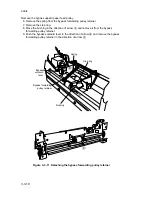
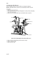
10. Remove the four screws holding the mirror 1 upper frame and then the frame.
Mirror 1 upper frame
Lamp wire
Screws
Screws
Mirror 1
lower frame
Wire retainers
Figure 3-3-29 Detaching the mirror 1 upper frame
11. Remove the two screws from each of the wire retainers and then the retainers from
the mirror 1 lower frame.
12. Remove the mirror 1 lower frame from the scanner unit.
Summary of Contents for Ri 4230
Page 3: ...SERVICE MANUAL Ri 4230 5230 ...
Page 13: ...4230 5230 S M MCA THEORY AND CONSTRUCTION SECTION I I Theory and Construction Section ...
Page 14: ...1 1 5 2A3 4 CONTENTS 1 1 Specifications 1 1 1 Specifications 1 1 1 ...
Page 100: ...4230 5230 S M MCA ELECTRICAL SECTION II II Electrical Section ...
Page 119: ......
Page 138: ......
Page 159: ...4230 5230 S M MCA III Set Up and Adjustment Section III SET UP AND ADJUSTMENT SECTION ...
Page 448: ...2A3 4 3 6 3 25 Toner scatters at the leading edge of the image See page 3 6 17 ...

