2A3/4
3-3-54
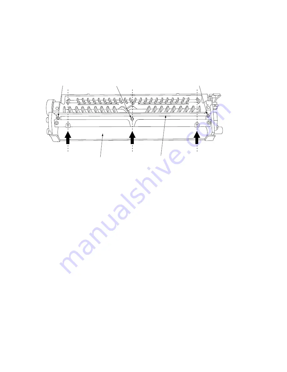
3. Measure the distance between the developing roller and the doctor blade with a
thickness gauge as shown in Figure 3-3-64, and adjust the doctor blade until the
correct distances are obtained at the center and ends of the developing unit
housing; the 0.50 mm gauge should go into the gap and the 0.55 mm one should
not.
∗
The smaller the distance, the lighter the image; the larger the distance, the darker
the image.
Adjustment screw
Developing roller
Adjustment screw
Adjustment screw
Doctor blade
Figure 3-3-64
Summary of Contents for Ri 4230
Page 3: ...SERVICE MANUAL Ri 4230 5230 ...
Page 13: ...4230 5230 S M MCA THEORY AND CONSTRUCTION SECTION I I Theory and Construction Section ...
Page 14: ...1 1 5 2A3 4 CONTENTS 1 1 Specifications 1 1 1 Specifications 1 1 1 ...
Page 100: ...4230 5230 S M MCA ELECTRICAL SECTION II II Electrical Section ...
Page 119: ......
Page 138: ......
Page 159: ...4230 5230 S M MCA III Set Up and Adjustment Section III SET UP AND ADJUSTMENT SECTION ...
Page 448: ...2A3 4 3 6 3 25 Toner scatters at the leading edge of the image See page 3 6 17 ...


