2A3/4
3-5-11
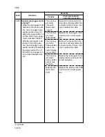
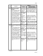
Scanner watchdog prob-
lem
• The main routine does not
run within 8.192 ms of the
main switch being turned
on.
Original detection posi-
tion problem
• The original size detection
microcomputer in the main
PCB cannot store initial
data correctly.
Polygon motor synchroni-
zation problem
• The polygon motor does
not reach the stable speed
within 9 s of the polygon
motor remote signal turn-
ing on.
Polygon motor steady-
state problem
• The polygon motor rotation
is not stable for 600 ms af-
ter the polygon motor rota-
tion has been stabilized.
C332
C340
C400
C401
Defective main
PCB.
Poor contact of
the connectors.
Defective origi-
nal size sensor.
Defective main
PCB or scan-
ner motor PCB.
Poor contact of
the polygon
motor connec-
tor terminals.
Defective poly-
gon motor.
Defective
power source
PCB.
Defective en-
gine PCB.
Poor contact of
the polygon
motor connec-
tor terminals.
Defective poly-
gon motor.
Replace the main PCB and
check for correct operation.
Check the connection of con-
nector CN7 on the scanner
motor PCB and the continuity
across the connector termi-
nals. Repair or replace if nec-
essary.
Replace the original size sen-
sor.
Replace the main PCB or
scanner motor PCB and check
for correct operation.
Reinsert the connector. Also
check for continuity within the
connector cable. If none, rem-
edy or replace the cable.
Replace the LSU.
Check if 24 V DC is supplied
to CN6-5 on the engine PCB.
If not, replace the power
source PCB.
Check if 24 V DC is output
from CN7-1 on the engine
PCB. If not, replace the engine
PCB.
Reinsert the connector. Also
check for continuity within the
connector cable. If none, rem-
edy or replace the cable.
Replace the LSU.
Code
Contents
Remarks
Causes
Check procedures/
corrective measures
Summary of Contents for Ri 4230
Page 3: ...SERVICE MANUAL Ri 4230 5230 ...
Page 13: ...4230 5230 S M MCA THEORY AND CONSTRUCTION SECTION I I Theory and Construction Section ...
Page 14: ...1 1 5 2A3 4 CONTENTS 1 1 Specifications 1 1 1 Specifications 1 1 1 ...
Page 100: ...4230 5230 S M MCA ELECTRICAL SECTION II II Electrical Section ...
Page 119: ......
Page 138: ......
Page 159: ...4230 5230 S M MCA III Set Up and Adjustment Section III SET UP AND ADJUSTMENT SECTION ...
Page 448: ...2A3 4 3 6 3 25 Toner scatters at the leading edge of the image See page 3 6 17 ...

