2A3/4
3-5-12
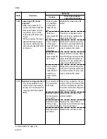
Defective
power source
PCB.
Defective en-
gine PCB.
Defective laser
diode.
Defective poly-
gon motor.
Defective main
PCB.
Defective high-
voltage trans-
former PCB.
Leakage during
main charging.
Defective high-
voltage trans-
former PCB.
Leakage during
transfer/sepa-
ration charging.
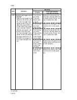
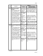
Poor contact of
the fixing unit
thermistor con-
nector termi-
nals.
Broken fixing
unit thermistor
wire.
Fixing unit ther-
mistor installed
incorrectly.
Fixing unit ther-
mostat
triggered.
Check if 24 V DC is supplied
to CN6-5 on the engine PCB.
If not, replace the power
source PCB.
Check if 24 V DC is output
from CN7-1 on the engine
PCB. If not, replace the engine
PCB.
Replace the LSU.
Replace the LSU.
Replace the main PCB.
Replace the high-voltage
transformer PCB.
Check and clean the main
charger assembly.
Replace the high-voltage
transformer PCB.
Check and clean the transfer
charger assembly.
Check the connection of con-
nector CN3-B8 on the engine
PCB and the continuity across
the connector terminals. Re-
pair or replace if necessary.
Measure the resistance. If it is
infinite, replace the fixing unit
thermistor.
Check and reinstall if neces-
sary.
Check for continuity. If none,
replace the fixing unit thermo-
stat.
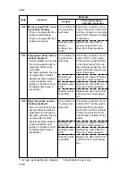
C401
C420
C510
C511
C610
Polygon motor steady-
state problem
• The polygon motor rotation
is not stable for 600 ms af-
ter the polygon motor rota-
tion has been stabilized.
BD steady-state problem
• The VTC detects a BD er-
ror for 600 ms after the
polygon motor rotation has
been stabilized.
Main charger problem
• MC ALM signal is detected
continuously for 400 ms
when MC REM signal is
turned on.
Transfer/separation high-
voltage problem
• STALM signal is detected
continuously for 400 ms
when TC/SC REM signal is
turned on.
Broken fixing unit ther-
mistor wire
• The fixing temperature
does not increase for 40 s
after the fixing heaters
have been turned on for
warming up.
• The fixing temperature re-
mains below 50˚C/122˚F
for 10 s continuously after
the fixing heaters have
been turned on during sta-
bilization.
Code
Contents
Remarks
Causes
Check procedures/
corrective measures
Summary of Contents for Ri 4230
Page 3: ...SERVICE MANUAL Ri 4230 5230 ...
Page 13: ...4230 5230 S M MCA THEORY AND CONSTRUCTION SECTION I I Theory and Construction Section ...
Page 14: ...1 1 5 2A3 4 CONTENTS 1 1 Specifications 1 1 1 Specifications 1 1 1 ...
Page 100: ...4230 5230 S M MCA ELECTRICAL SECTION II II Electrical Section ...
Page 119: ......
Page 138: ......
Page 159: ...4230 5230 S M MCA III Set Up and Adjustment Section III SET UP AND ADJUSTMENT SECTION ...
Page 448: ...2A3 4 3 6 3 25 Toner scatters at the leading edge of the image See page 3 6 17 ...


