2A3/4
3-5-19
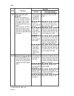
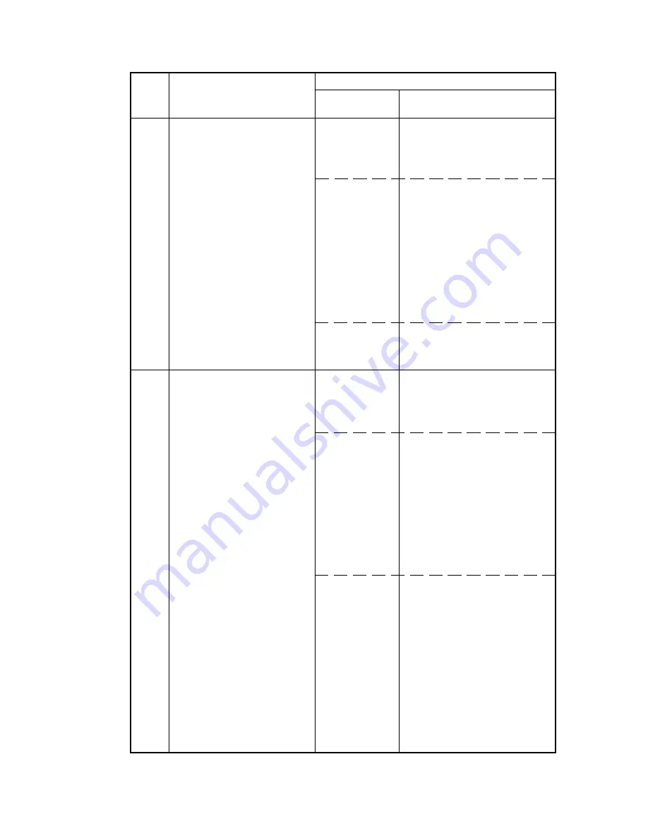
The front sta-
pler connector
makes poor
contact.
The front sta-
pler malfunc-
tions.
a) The front
stapler is
blocked with a
staple.
b) The front
stapler is bro-
ken.
Defective fin-
isher main
PCB.
The rear sta-
pler connector
makes poor
contact.
The rear sta-
pler malfunc-
tions.
a) The rear sta-
pler is blocked
with a staple.
b) The rear sta-
pler is broken.
Defective fin-
isher main
PCB.
Reinsert the connector. Also
check for continuity within the
connector cable. If none, rem-
edy or replace the cable.
a) Remove the front stapler
cartridge, and check the car-
tridge and the stapling section
of the stapler.
b) Replace the front stapler
and check for correct opera-
tion.
Replace the finisher main PCB
and check for correct opera-
tion.
Reinsert the connector. Also
check for continuity within the
connector cable. If none, rem-
edy or replace the cable.
a) Remove the rear stapler
cartridge, and check the car-
tridge and the stapling section
of the stapler.
b) Replace the rear stapler
and check for correct opera-
tion.
Replace the finisher main PCB
and check for correct opera-
tion.
C821
C822
Finisher front stapler
problem*
2
• The front stapler home po-
sition sensor does not
change state from non-de-
tection to detection within
0.2 s of the start of front
stapler motor counterclock-
wise (forward) rotation.
• During initialization, the
front stapler home position
sensor does not change
state from non-detection to
detection within 0.6 s of the
start of front stapler motor
clockwise (reverse) rota-
tion.
Finisher rear stapler prob-
lem*
2
• The rear stapler home po-
sition sensor does not
change state from non-de-
tection to detection within
0.2 s of the start of rear
stapler motor counterclock-
wise (forward) rotation.
• During initialization, the
rear stapler home position
sensor does not change
state from non-detection to
detection within 0.6 s of the
start of rear stapler motor
clockwise (reverse) rota-
tion.
Code
Contents
Remarks
Causes
Check procedures/
corrective measures
*2: optional.
Summary of Contents for Ri 4230
Page 3: ...SERVICE MANUAL Ri 4230 5230 ...
Page 13: ...4230 5230 S M MCA THEORY AND CONSTRUCTION SECTION I I Theory and Construction Section ...
Page 14: ...1 1 5 2A3 4 CONTENTS 1 1 Specifications 1 1 1 Specifications 1 1 1 ...
Page 100: ...4230 5230 S M MCA ELECTRICAL SECTION II II Electrical Section ...
Page 119: ......
Page 138: ......
Page 159: ...4230 5230 S M MCA III Set Up and Adjustment Section III SET UP AND ADJUSTMENT SECTION ...
Page 448: ...2A3 4 3 6 3 25 Toner scatters at the leading edge of the image See page 3 6 17 ...


