ROYAL ENFIELD WORKSHOP MANUAL
PAGE 93
P1
Accessories
1. Legshields
Legshield (Part Nos. 41399 and 41400) are
available for the 1958 to 1963 "250 Clipper" and
the 1957 to 1962 "Crusader 250." They are made
from steel pressings and, being of double
curvature, are particularly robust. Their method of
attachment ensures no vibration.
Underneath the tank and welded to the tank
tube of the frame is a clip provided for the top
attachment of the legshields. The crossbar (41550)
is attached to this clip with stud (31160), distance
piece (41551), two nuts (27944) and washers
(27917). Do not tighten the nuts until the
legshields have been fitted, as the crossbar can
slide and pivot in the clip for adjustment. The
legshields are attached to this bar with screws
(14446), and washers (27917). Rubber grommets
(40183) are fitted over the bar where it passes
through the legshields. For the bottom attachment
the middle engine plate stud is replaced by stud
(42892). Distance tubes (41552, L.H.) and (42893,
R.H.) are fitted between the engine plates and
legshield brackets, and the original nuts and
washers used to hold the assembly together.
2. Pannier Equipment
Pannier bags (42218), and carriers (42193) and
(42194), specially designed for the "250 Clipper,"
"Crusader" and "Crusader Sports," can be fitted
after very little modification. The carriers, made
from steel pressings, prevent any dirt from the
back wheel soiling the bags.
Each pannier carrier is attached at three points.
The forward end is clipped to the mudguard carrier
tube with two clips (Part No. 42196), and two
screws (42202). The screw heads are on the outside
with a large washer (5965) under each head and a
collar (23941) between the carrier and each end of
the outer clip. Use nuts (27944) and washers
(27917). A strut (42199) is attached to the rear
mudguard behind the dual seat by the existing
screws holding the mudguard to the mudguard
bridge. Each carrier is fastened to the strut with a
screw (42203) and two washers (5965), one
between the strut and the carrier, the other
between the carrier and the head of the screw. Drill
21
/
64
in. dia. hole in the valance of the mudguard in
line with the bottom fixing hole of each pannier
carrier. Position the mudguard bridge (40053) to
suit these holes drilled in the valance, and drill two
9
/
32
in. dia. holes through the guard to line up with
the two in the bridge. Attach the bridge to the
guard with screws (18446), nuts (26998) and
washers (27916). Place a short distance piece
(20199) between the bridge and the inside of the
valance and a longer distance piece (42201) and
washer (5965) between the valance and back of the
carrier, the washer being next to the carrier. A bolt
(42204) with washer (5965) under the head is fitted
from the outside and tightened up with nut (27944)
and washer (8634).
"Airflow" Fairing
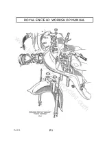
1. Description of the fairing
The "Airflow" fairing and front mudguard are
fibre glass units and therefore very light, rigid and
tough. The fairing, with the windscreen, provides
full weather protection. It has two cubby holes
and incorporates the headlamp, speedometer,
ammeter and lighting switch.
On the rare occasions that it may be necessary
to remove the mudguard and fairing from the
machine, it will be found to present no difficulty if
the following sequence is adopted:
2. Removal of the
Windscreen
Remove the two screws which attach the
number plate to the fairing. Removal of the
number plate will expose a screw in the centre of
the fairing which may now be taken out, together
with the screws at each corner of the screen. The
screen and metal back plate may now be lifted
clear, taking care not to lose the five slotted sleeve
nuts with their plain steel and rubber washers.
3. Removal of the
Headlamp
Take out the small screw from the underside
of the headlamp rim. Raise the rim to clear its
spigot plate from the slot in the lamp body shell
and remove. Next take off the rubber ring from
the light unit. By slackening the three light unit
adjuster screws and rotating the light unit in an
anti-clockwise direction, the unit may then be
withdrawn sufficiently to disconnect the four
leads.
Should it be necessary to remove the lamp
body shell this may be done by unscrewing the
four screws spaced round its flange. This also
releases the rubber washer. Care should be taken
not to lose the four screw locking plates inside the
fairing.
4. Removal of the Headlamp Switch,
Speedometer
and Ammeter
Undo the switch knob screw and remove the
knob. Unscrew the switch plate nut and remove
the switch plate. The switch body may now be
pulled out from beneath the fairing. Do not lose
the plain washer situated beneath the switch knob.
Disconnect the speedometer drive, and, after
removing two nuts, the spring washers and the
bridge piece from the bottom of the
speedometer, it may be removed.
To remove the ammeter it is only necessary to
take off the rubber band from the body of the
ammeter, after disconnecting the leads, and press
down the small metal tabs which will be found
turned outwards. The ammeter will then pull out
from the top of the fairing.
5. Removal of the Front Wheel and Fork Legs
To remove the front wheel from the fork,
place the machine on the centre stand with
sufficient packing (about 2 in.) beneath each side
of the stand to lift the wheel clear off the ground
when tilted back on to the rear wheel. Slacken the
brake cable adjustment and disconnect the cable
from the handlebar lever and from the operating
cam lever on the hub. Unscrew the four nuts
securing the fork leg caps and allow the wheel to
drop forward out of the front fork. Make sure
that the machine stands securely on the rear wheel
and centre stand-if necessary place a weight on
the saddle or a strut beneath the fork to ensure
this.
Unscrew the plug screws in the fork head,
when the sliding fork legs, complete with springs
and spring distance tubes, can be withdrawn from
the lower ends of the main tubes.
6. Removal of the Front Mudguard
From the top of the fairing the two clamp
bolts holding the mudguard to the fork crown can
be reached. Unscrew the nuts and push out the
bolts.
On Early Models it is necessary to remove the
centre pin securing the guard to the bottom of the
steering stem. The mudguard may now be
withdrawn.
7. Removal of the Fairing
First take off the exhaust pipe. This is held to
one of the front engine bearer bolts and to the
pillion footrest stud at the rear.
Slacken the hose clips and remove the attach-
ment caps from the ends of the attachment studs
to which the lower part of the fairing is anchored.
Unscrew the nuts and push out the stud which
secures the upper part of the fairing to the tube
extending forward from the steering head.
If desired the two bottom attachment studs
may be removed.
www.hitchcocksmotorcycles.com
Summary of Contents for 250 CLIPPER
Page 40: ...ROYAL ENFIELD WORKSHOP MANUAL PAGE 40 w w w h i t c h c o c k s m o t o r c y c l e s c o m ...
Page 46: ...ROYAL ENFIELD WORKSHOP MANUAL PAGE 46 w w w h i t c h c o c k s m o t o r c y c l e s c o m ...
Page 52: ...ROYAL ENFIELD WORKSHOP MANUAL PAGE 52 w w w h i t c h c o c k s m o t o r c y c l e s c o m ...
Page 62: ...ROYAL ENFIELD WORKSHOP MANUAL PAGE 62 w w w h i t c h c o c k s m o t o r c y c l e s c o m ...
Page 72: ...ROYAL ENFIELD WORKSHOP MANUAL PAGE 72 w w w h i t c h c o c k s m o t o r c y c l e s c o m ...
Page 76: ...ROYAL ENFIELD WORKSHOP MANUAL PAGE 76 w w w h i t c h c o c k s m o t o r c y c l e s c o m ...
Page 88: ...ROYAL ENFIELD WORKSHOP MANUAL PAGE 88 w w w h i t c h c o c k s m o t o r c y c l e s c o m ...


