ROYAL ENFIELD WORKSHOP MANUAL
Section L12 Page 3
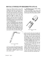
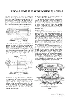
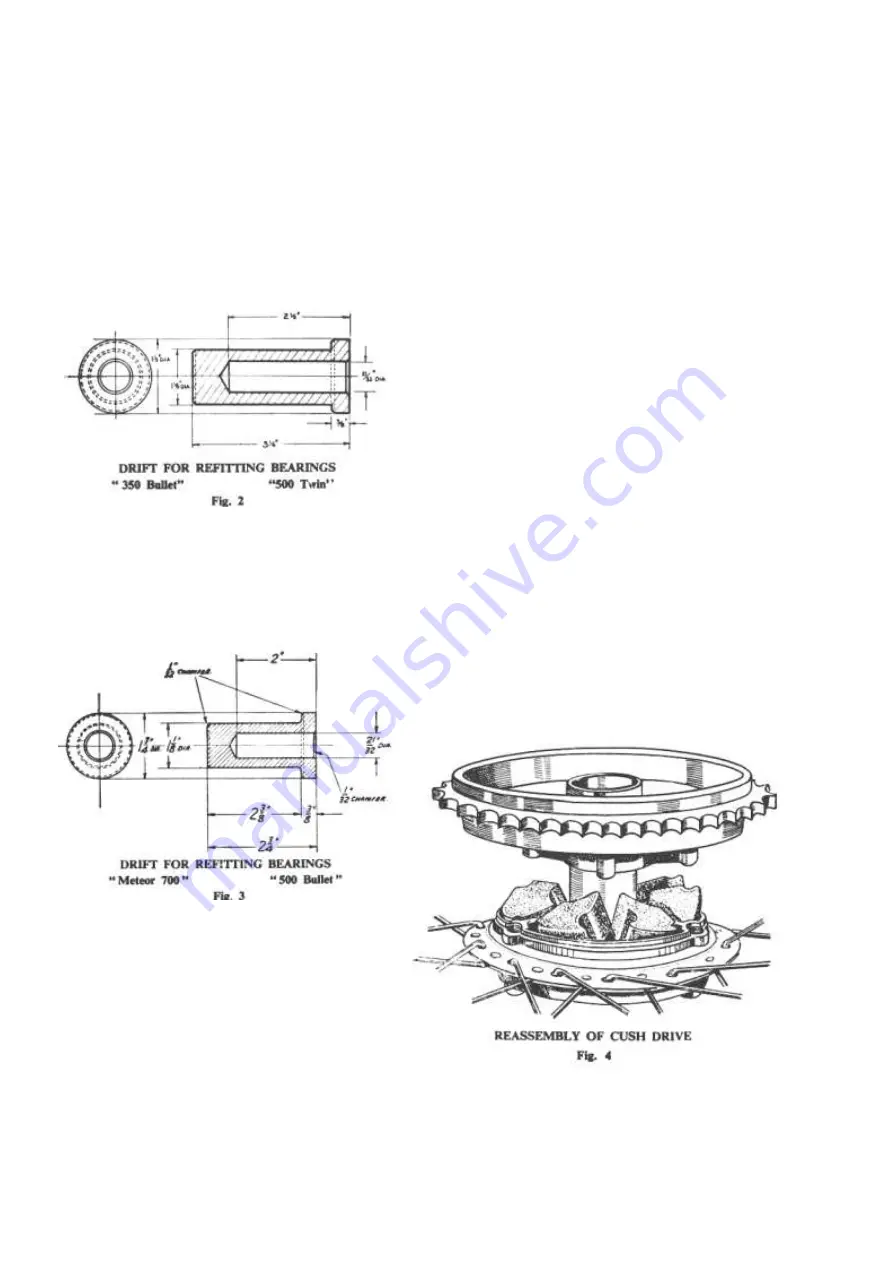
are then entered into one end of the hub barrel
which is then supported on one of the hollow
drifts. The other bearing is then threaded over the
upper end of the spindle and driven home by
means of the second hollow drift either under a
press or by means of a hammer which will thus
drive both bearings into position simultaneously.
In order to make quite sure that there is
clearance between the inner faces of the outer
bearings and the bottom of the recesses fit the
distance washers against the inner races of the
bearings and either fit the assembly of brake cover
plate, speedometer gearbox, etc., or make up this
distance with tubular distance pieces. Fit and
tighten the spindle nuts. Tightening the nuts
should not have any effect on the ease with which
the spindle can be turned. If tightening the nuts
makes the spindle hard to turn this may be taken
as proof that the bearings are bottoming in the
recesses in the hub barrel before they are solid
against the shoulders on the spindle. In this case
the bearing should be removed and a thin packing
shim fitted between the inner race and the
shoulder on the spindle.
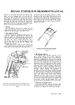
9. Removal of Brake Operating Cam and
Brake Shoe Pivot Pin
The method of doing this has already been
described in Paragraph 3 dealing with the 6 in.
brake. The method is precisely the same for the 7
in. brake except that, owing to the different type
of return springs used, it is, in this case, possible
to remove the shoes from the pivot pin and
operating cam before the latter are removed from
the cover plate.
10. Cush Drive
The sprocket/brake drum is free to rotate on
the hub barrel. Three radial vanes are formed on
the back of the brake drum and three similar
vanes are formed on the cush drive shell. Six
rubber blocks are fitted between the vanes on the
brake drum and those on the cush drive shell,
thus permitting only a small amount of angular
movement of the sprocket/brake drum relative to
the hub barrel and transmitting both driving and
braking torque and smoothing out harshness and
irregularity in the former.
If the cush drive rubbers become worn so
that the amount of free movement measured at
the tyre exceeds 1/2 in. to 1 in., the rubbers
should be replaced. To obtain access to them
remove the complete wheel as described above,
remove the brake cover plate complete with the
brake shoe assembly, unscrew the three locknuts
at the back of the cush drive shell-if necessary
holding the studs, 32431, by means of the flats on
the heads inside the brake drum. Drive out the
three studs into the brake drum after which the
sprocket/brake drum can be separated from
www.hitchcocksmotorcycles.com
Summary of Contents for 350 BULLET 1956
Page 7: ...ROYAL ENFIELD WORKSHOP MANUAL w w w h i t c h c o c k s m o t o r c y c l e s c o m ...
Page 57: ...ROYAL ENFIELD WORKSHOP MANUAL w w w h i t c h c o c k s m o t o r c y c l e s c o m ...
Page 69: ...ROYAL ENFIELD WORKSHOP MANUAL w w w h i t c h c o c k s m o t o r c y c l e s c o m ...
Page 77: ...ROYAL ENFIELD WORKSHOP MANUAL w w w h i t c h c o c k s m o t o r c y c l e s c o m ...

