ROYAL ENFIELD WORKSHOP MANUAL
Section C14 Page 2
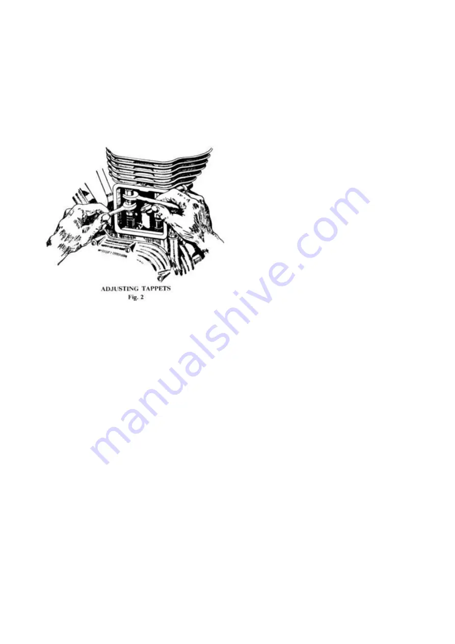
stems and rockers, with the rocker box covers
removed. To remove the rocker box covers the
petrol tank must be taken off. (See Subsection 5.)
The correct clearance is nil or as little as
possible with the engine COLD.
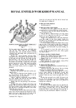
To make the adjustment hold the push rod
bottom end (top hexagon) and turn the locknut
(middle hexagon) to the left. Screw the push rod
cup (bottom hexagon) to the left to take up
clearance or to the right to increase the clearance,
at the same time holding the push rod bottom end
(top hexagon). Lock the adjustment by tightening
the locknut against the push rod end and then
recheck the clearance.
Owing to the initial bedding down of the
wearing surfaces, the tappets on new engines may
require adjustment after the first few hundred
miles.
4. Ignition Timing
The setting of the ignition depends upon the
position of the magneto or contact breaker drive
pinion relative to the shaft.
To obtain access to the pinion it is necessary to
remove the timing cover (see Subsection 1).
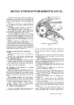
On engines fitted with magneto and
autoadvance mechanism, the latter is in unit with
the driving pinion, and is held to the shaft on a
smooth taper and secured by a nut having a
right-hand thread.
There is some difference in all "350 Clipper"
(see subsection 18) and all "Trials" models, and in
"350 and 500 Bullets" from 1960 onwards.
To remove the pinion and the auto-advance
device, unscrew the nut and this will draw the
pinion off.
Before setting the timing remove the magneto
cover and adjust the contact breaker points to a
clearance of .015 in. when fully opened.
Because of the auto-advance mechanism, the
timing is normally in the "retard" position when
the engine is stationary. Rotate the two halves of
the coupling relatively to each other against the
springs, i.e. into the "advance" position, and hold
it in this position by a piece of wire.
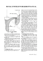
To set the timing, turn the engine until the
piston is 1/2-7/16 in. for the 350 c.c. Engine, or
3/8-5/16 in. for the 500 c.c. Engine, before top
dead centre on the compression stroke, i.e. with
both valves closed.
Insert a thin piece of paper between the point
of the contact breaker and turn the magneto
forwards (or clockwise looking on the contact
breaker) until the paper can just be pulled out.
Tighten the pinion and auto-advance device on
to the shaft, taking care that it does not slip.
Remove the piece of wire holding the
auto-advance mechanism.
The timing can be checked by removing the cap
from the magneto and holding the rotor in the
advanced position by means of a screwdriver,
without the necessity of taking off the timing
cover.
On no account must the cam be altered
from its original position on the rotor shaft or
the efficiency of the magneto will be affected.
For all "350 Clippers," the auto-advance
mechanism used is of a different type from that on
the "350 Bullet" up to 1959, and the engine must
be checked and set in the fully retarded position.
This and the following remarks apply to "350 and
500 Bullets," 1960 onwards.
Gap setting should be .015 in. to .018 in. and
the engine should be timed so that the contact are
on the point of opening when the piston is 1/16 in.
before top dead centre.
The best way to check the opening point is to
switch on the ignition and rotate the engine slowly
until the ammeter needle returns to its central
position.
To adjust the timing, slacken the clamping bolt
on the contact breaker housing and rotate the
housing. If the timing cover has been dismantled,
start with the contact breaker housing so that the
name on the cover is roughly horizontal.
"Works Replica." The contact breaker should
be set so that the points are just breaking when the
piston is 7/16 in. before top dead centre on the
compression stroke, ignition fully advanced.
5. Removal of the Petrol Tank
Turn off the petrol tap.
Disconnect the petrol pipe.
Remove the bolt which holds the front of the
tank to the frame, pull upward, to release the
spring clip holding the tank at the rear.
www.hitchcocksmotorcycles.com
Summary of Contents for 350 BULLET 1956
Page 7: ...ROYAL ENFIELD WORKSHOP MANUAL w w w h i t c h c o c k s m o t o r c y c l e s c o m ...
Page 57: ...ROYAL ENFIELD WORKSHOP MANUAL w w w h i t c h c o c k s m o t o r c y c l e s c o m ...
Page 69: ...ROYAL ENFIELD WORKSHOP MANUAL w w w h i t c h c o c k s m o t o r c y c l e s c o m ...
Page 77: ...ROYAL ENFIELD WORKSHOP MANUAL w w w h i t c h c o c k s m o t o r c y c l e s c o m ...


