WORKSHOP MANUAL BULLET
Page 24
10. Removal of Engine and Clutch sprockets
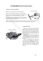
Remove the alternator stator by undoing three nuts. The primary chain is endless hence it is
necessary to remove both the engine and clutch sprockets simultaneously. Remove the central
hexagon nut securing the alternator rotor, which can then be drawn off, taking care not to lose the key.
The engine sprocket is mounted on splines and can be removed along with the clutch sprocket using
extractor 2004.
11. Removal of Final Drive Sprocket
Remove the clutch as described above. Remove the primary chain tensioner. Remove the primary
chaincase inner by removing three nuts. Remove the folding of the tab washer which is provided for
locking the final drive sprocket nut. Hold the sprocket and remove the nut (right hand thread). The
sprocket can then be withdrawn.
12. Re-assembly of the Clutch Plates
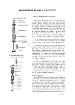
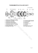
When re-assembling the clutch plates the following order must be observed. The clutch pad must
be fitted into the main drive shaft, plain dished plate (dish projecting out wards), friction plate with
inserts, plain flat plate, friction plate bonded, plain dished plate (dish projecting inwards) friction
plate bonded, clutch front plate, 3 springs on the clutch centre lugs.
The other three springs are located by
means of bosses on the clutch cap. Tighten
the spring pins as far as they will go. If the
clutch lifts unevenly, it is probable that one
of the springs has taken a set, in which case
new spring should be fitted.
The friction plate with inserts should be renewed if badly worn or when the inserts have become
loose in their plate. The bonded friction plates require renewal when worn or charred. (A light change
to a blackish colour should not be mistaken as charred).
Excessive or premature wear of the plates is due to either running the vehicle at half clutch
application or depriving the clutch plates of oil, with insufficient or no oil in the clutch chain case.
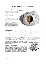
13. Primary Chain Adjustment
Access to the primary chain adjuster is gained by removing the primary chain cover which is held
in position by a single nut. Before removing the nut, place a tray under the engine to collect the oil
from the chaincase.
Beneath the bottom run of the chain is a curved slipper chain tensioner pad on which the chain
rests. This can be raised or lowered by turning the adjusting screw below the chain tensioner pad after
having first slackened the locknut.
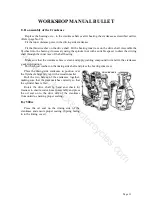
CLUTCH ASSEMBLY
www.hitchcocksmotorcycles.com
Summary of Contents for 350 BULLET 1989
Page 9: ...WORKSHOP MANUAL BULLET Page 9 w w w h i t c h c o c k s m o t o r c y c l e s c o m ...
Page 17: ...w w w h i t c h c o c k s m o t o r c y c l e s c o m ...
Page 34: ...WORKSHOP MANUAL BULLET Page 34 w w w h i t c h c o c k s m o t o r c y c l e s c o m ...
Page 37: ...w w w h i t c h c o c k s m o t o r c y c l e s c o m ...
Page 41: ...WORKSHOP MANUAL BULLET Page 41 w w w h i t c h c o c k s m o t o r c y c l e s c o m ...
Page 58: ...WORKSHOP MANUAL BULLET Page 58 w w w h i t c h c o c k s m o t o r c y c l e s c o m ...
Page 69: ...WORKSHOP MANUAL BULLET Page 69 w w w h i t c h c o c k s m o t o r c y c l e s c o m ...
Page 73: ...w w w h i t c h c o c k s m o t o r c y c l e s c o m ...
Page 77: ...w w w h i t c h c o c k s m o t o r c y c l e s c o m ...
Page 103: ...w w w h i t c h c o c k s m o t o r c y c l e s c o m ...
Page 105: ...w w w h i t c h c o c k s m o t o r c y c l e s c o m ...
Page 107: ...WORKSHOP MANUAL BULLET Page 107 w w w h i t c h c o c k s m o t o r c y c l e s c o m ...
Page 108: ...WORKSHOP MANUAL BULLET Page 108 w w w h i t c h c o c k s m o t o r c y c l e s c o m ...
Page 109: ...WORKSHOP MANUAL BULLET Page 109 w w w h i t c h c o c k s m o t o r c y c l e s c o m ...
Page 110: ...WORKSHOP MANUAL BULLET Page 110 w w w h i t c h c o c k s m o t o r c y c l e s c o m ...
Page 111: ...WORKSHOP MANUAL BULLET Page 111 w w w h i t c h c o c k s m o t o r c y c l e s c o m ...
Page 113: ...WORKSHOP MANUAL BULLET Page 113 w w w h i t c h c o c k s m o t o r c y c l e s c o m ...

