WORKSHOP MANUAL BULLET
Page 30
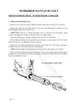
FLYWHEEL IN A JIG
FLYWHEEL ASSEMBLY
7. Flywheel Assembly
The flywheel assembly consists of the crankshaft and the connecting rod.
To dismantle the crankshaft remove the set screws securing the crankpin nuts. Holding the crankshaft
in a special jig (2037) remove the crankpin nuts.
Using 2037, with a pair of steel bars (about 1" x 3/8 x 9" long) placed across, between the flywheel
disc, press out the crankpin using a hand press.
The connecting rod can then be removed along with floating bush.
Turn the crankshaft over in the jig and repeat with other side if necessary. To remove the timing shaft,
remove the set screw from the shaft nut and unscrew the nut. Drive the shaft out with a hammer and
drift.
To replace the timing side shaft, reverse the above process, making
sure that the key is a good fit and that the nut is tightened securely by
means of a box spanner with a 12" tommy bar.
The driving shaft has no nut but is secured by tightening the sprocket
nut after the assembly of the engine. It should be pressed in with a
hand press or a hammer and drift. If the latter is used care must be
taken not to damage the centre. It has a collar which butts against the
flywheel disc.
To reassemble the crankshaft, press the crankpin into the timing side
flywheel, making sure that the oil hole is in the correct position and
the thrust washer is facing the right way, ie. with chamfer away from
the flywheel.
Test the oil passages using an oil can to make sure that they are clear.
Assemble the floating bush over the crankpin.
Assemble the connecting rod over the floating bush and smear engine oil.
Place the other thrust washer over the crankpin, also with the chamfer away from the flywheel.
Use a brass drift and hammer for pressing the D/S flywheel.
Locate the flywheel in the assembly jig, to ensure that the flywheels and shafts are in line and replace
the nuts, tighten securely and refit the set screws.
Test the oil passages again to ensure that they are clear.
If the same crankpin has been put back, it will be necessary to
drill out the old grub screw, in order to clean the oil passages
after which a new grub screw must be fitted.
Mount the crankshaft between the centres of a lathe or on a
pair of “v” block and true up to .001" on either side of the
shafts.
If the readings for the two shafts are high on opposite sides, the
error can be corrected by gently tapping either or both of the
flywheels.
If the readings are high on the same side of the two shafts, it is
probably due to dirt or foreign matter in the joints and the
crankshaft should be dismantled again, carefully examined and
cleaned and re-assembled.
www.hitchcocksmotorcycles.com
Summary of Contents for 350 BULLET 1989
Page 9: ...WORKSHOP MANUAL BULLET Page 9 w w w h i t c h c o c k s m o t o r c y c l e s c o m ...
Page 17: ...w w w h i t c h c o c k s m o t o r c y c l e s c o m ...
Page 34: ...WORKSHOP MANUAL BULLET Page 34 w w w h i t c h c o c k s m o t o r c y c l e s c o m ...
Page 37: ...w w w h i t c h c o c k s m o t o r c y c l e s c o m ...
Page 41: ...WORKSHOP MANUAL BULLET Page 41 w w w h i t c h c o c k s m o t o r c y c l e s c o m ...
Page 58: ...WORKSHOP MANUAL BULLET Page 58 w w w h i t c h c o c k s m o t o r c y c l e s c o m ...
Page 69: ...WORKSHOP MANUAL BULLET Page 69 w w w h i t c h c o c k s m o t o r c y c l e s c o m ...
Page 73: ...w w w h i t c h c o c k s m o t o r c y c l e s c o m ...
Page 77: ...w w w h i t c h c o c k s m o t o r c y c l e s c o m ...
Page 103: ...w w w h i t c h c o c k s m o t o r c y c l e s c o m ...
Page 105: ...w w w h i t c h c o c k s m o t o r c y c l e s c o m ...
Page 107: ...WORKSHOP MANUAL BULLET Page 107 w w w h i t c h c o c k s m o t o r c y c l e s c o m ...
Page 108: ...WORKSHOP MANUAL BULLET Page 108 w w w h i t c h c o c k s m o t o r c y c l e s c o m ...
Page 109: ...WORKSHOP MANUAL BULLET Page 109 w w w h i t c h c o c k s m o t o r c y c l e s c o m ...
Page 110: ...WORKSHOP MANUAL BULLET Page 110 w w w h i t c h c o c k s m o t o r c y c l e s c o m ...
Page 111: ...WORKSHOP MANUAL BULLET Page 111 w w w h i t c h c o c k s m o t o r c y c l e s c o m ...
Page 113: ...WORKSHOP MANUAL BULLET Page 113 w w w h i t c h c o c k s m o t o r c y c l e s c o m ...

