WORKSHOP MANUAL BULLET
Page 75
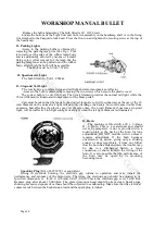
the second groove (from top) in its lock washer. When assembling make sure that the jet needle can
move freely in the slide. The lock washer must be put with its outer fork into the narrow rim inside
the throttle slide so that the space in the slide for fixing the cable is not obstructed. Then place on
the lock washer a Disc which has four cut out portions to accommodate the rims inside the slide.
The latter ensure that the throttle slide spring presses only on the throttle slide itself. When the
throttle slide is only slightly open the so-called ‘CUTAWAY’ in the slide, i.e. a small space at the
lower edge of same, has an additional influence on the fuel quantity delivered. A small cutaway
causes an enriched fuel mixture in that range and vice versa.
IDLING SYSTEM
For idling of the engine the throttle slide is closed to the point where it touches the
throttle
stop screw. With this screw the idling r.p.m can be varied. Turning clockwise increases the idling
speed and vice versa. The throttle stop screw is prevented from loosening by spring.
In the idling position the vacuum at the needle jet outlet is so small that no fuel is delivered
through the main control system. The fuel to be mixed with the indrawn air in this range is
delivered through a supplementary system.
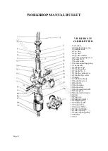
The fuel coming from the float bowl feeds the idling jet which regulates the fuel quantity.
Behind the jet orifice air is added through holes at the jet needle. The quantity of air is determined
by the position of the air adjusting screw. The
preliminary mixture enters the carburettor bore
through the idling outlet where a further mixture with filtered air takes place. The air adjusting
screw is secured with a spring.
Setting of the air adjusting screw is as follows:
Close fully by turning clockwise and open (anti-clockwise) by 2 turns.
The setting indicated can give only general data. Sometimes it may be necessary to readjust.
This should always be done when the engine is warm.
Select the desired idling speed with the throttle stop screw as described above. The air
adjusting screw is now opened (anti-clockwise) till the speed increases slightly. Then close the
screw again a quarter turn.
The adjusting screw for cable of the throttle slide must be turned into a point where the outer
cable has about 3 mm play. This guarantees that in idling the throttle slide touches the throttle stop
screw, and the cable does not interfere with the setting of the idling. The cable should be lubricated
from time to time.
STARTING SYSTEM
To enrich the mixture drawn in (especially for starting a cold engine) the carburetter
incorporates a secondary much smaller and simpler slide carburetter. i.e. a so-called starting
carburetter. When its slide-the starting piston is lifted by means of a lever against the pressure of
spring the engine suction delivers additional fuel through starting jet Std and its standpipe. During
this operation the throttle slide is fully closed.
SERVICING OF THE CARBURETTER
Cleaning the carburetter which may be necessary from time to time, depending on the amount
of dust present is done best with petrol. First clean the outside of the carburetter. Always use
suitable tools for taking it apart.
Check whether All parts are still in perfect condition. Worn-out float needles, needle jets, jet
needles and throttle slides should be replaced as they are mentioned before considerably affect the
power and consumption of the engine. Clogged jets should be cleaned by blowing through never
clean with a hard object. If necessary clean also the idling outlet hole either with compressed air or
a wood splinter. Damaged gaskets should be replaced. Please note that when fitting spare parts only
the use of GENUINE BING Spare parts guarantee satisfactory performance of the carburetter.
www.hitchcocksmotorcycles.com
Summary of Contents for 350 BULLET 1989
Page 9: ...WORKSHOP MANUAL BULLET Page 9 w w w h i t c h c o c k s m o t o r c y c l e s c o m ...
Page 17: ...w w w h i t c h c o c k s m o t o r c y c l e s c o m ...
Page 34: ...WORKSHOP MANUAL BULLET Page 34 w w w h i t c h c o c k s m o t o r c y c l e s c o m ...
Page 37: ...w w w h i t c h c o c k s m o t o r c y c l e s c o m ...
Page 41: ...WORKSHOP MANUAL BULLET Page 41 w w w h i t c h c o c k s m o t o r c y c l e s c o m ...
Page 58: ...WORKSHOP MANUAL BULLET Page 58 w w w h i t c h c o c k s m o t o r c y c l e s c o m ...
Page 69: ...WORKSHOP MANUAL BULLET Page 69 w w w h i t c h c o c k s m o t o r c y c l e s c o m ...
Page 73: ...w w w h i t c h c o c k s m o t o r c y c l e s c o m ...
Page 77: ...w w w h i t c h c o c k s m o t o r c y c l e s c o m ...
Page 103: ...w w w h i t c h c o c k s m o t o r c y c l e s c o m ...
Page 105: ...w w w h i t c h c o c k s m o t o r c y c l e s c o m ...
Page 107: ...WORKSHOP MANUAL BULLET Page 107 w w w h i t c h c o c k s m o t o r c y c l e s c o m ...
Page 108: ...WORKSHOP MANUAL BULLET Page 108 w w w h i t c h c o c k s m o t o r c y c l e s c o m ...
Page 109: ...WORKSHOP MANUAL BULLET Page 109 w w w h i t c h c o c k s m o t o r c y c l e s c o m ...
Page 110: ...WORKSHOP MANUAL BULLET Page 110 w w w h i t c h c o c k s m o t o r c y c l e s c o m ...
Page 111: ...WORKSHOP MANUAL BULLET Page 111 w w w h i t c h c o c k s m o t o r c y c l e s c o m ...
Page 113: ...WORKSHOP MANUAL BULLET Page 113 w w w h i t c h c o c k s m o t o r c y c l e s c o m ...


