ROZUM ROBOTICS
PULSE robotic arm
Page
19 | 23
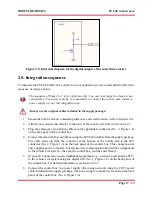
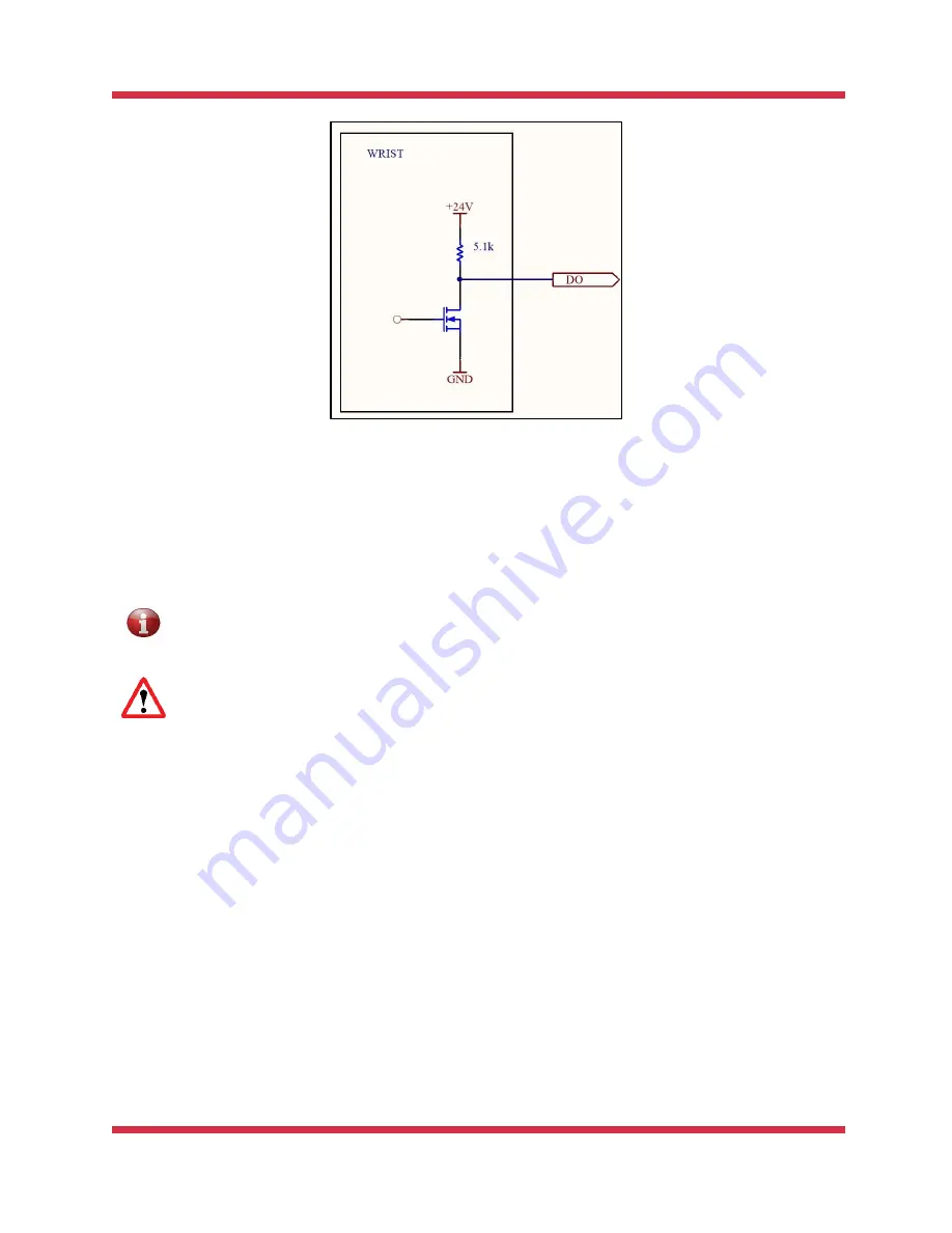
Figure 2-5: Electrical diagram for the digital outputs of the end effector socket
2.5. Integration sequence
To integrate the PULSE robotic arm system into your application, it is recommended to follow the
sequence of steps as below:
The sequence of Steps 2 to 7 is for reference only. You can re-arrange the steps at your
convenience. For safety reasons, it is advisable to connect the robotic arm system to
power supply as your last integration step.
Always use the original cables included in the supply package!
1.
Mount the robotic arm on a mounting surface at a selected location (refer to Section 2.2).
2.
Attach your selected end effector to the wrist of the robotic arm (refer to Section 2.4).
3.
Plug the emergency stop button cable into the appropriate connector (No. 7, Figure 1-6)
on the back panel of the control box.
4.
Connect the arm with the control box using the 48V hybrid cable from the supply package.
The cable must run from the connector at the bottom of the robotic arm to the 48V
connector (No. 8, Figure 1-6) on the back panel of the control box. This connection not
only supplies power to the arm, but also provide communication between the components
of the robotic arm system—the arm, the control box, and the end effector.
5.
(
Optional
) Connect any required additional equipment (e.g., a sensor, a safeguard, a PLC)
to the robotic arm system using the digital I/Os (No. 1, Figure 1-6) on the back panel of
the control box. For detailed information, see Section 2.3.3.
6.
Connect the control box to a power supply (the mains network) using the 220V power
cable included in the supply package. The power supply connector is located on the back
panel of the control box (No. 4, Figure 1-6).
Summary of Contents for Pulse
Page 1: ......


