background image

ROZUM ROBOTICS


PULSE DESK


Rev. 5, in effect from Q2 2019 

Page


20 | 56


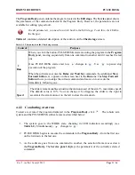
Figure 3-2

:

 The Main menu of PULSE DESK 

4


PROGRAMMING WITH PULSE DESK 

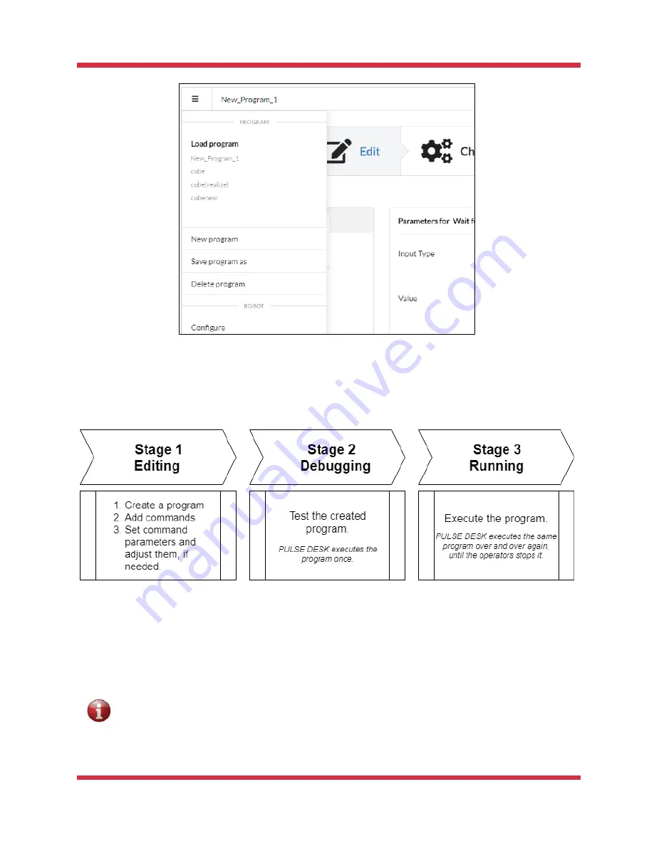
The general workflow of the PULSE DESK software is as illustrated in 

Figure 4-1

. 


Figure 4-1: The PULSE DESK workflow 

Until you complete the entire workflow up to the 

Run

 stage, switching from stage to stage is only 

possible in the consecutive manner by stage names in the 

Stepper

 or the 

Next 

button

Once you 

are at the 

Run 

stage, you can switch between the stages randomly by clicking the stage names in 

the Stepper —

 Edit

Check

 or 

Run


Before switching back from the Run stage to any other, it is advisable to stop program 
execution. 

Summary of Contents for Pulse

Page 1: ......

Page 2: ...ng the arm 11 2 2 Setting communication with the PULSE arm 12 2 2 1 Static IP 12 Windows OS 12 Linux OS 14 2 2 2 Dynamic IP 16 3 THE PULSE DESK USER INTERFACE 16 3 1 Accessing the PULSE DESK software 17 3 2 Edit screen 17 3 3 The Main Menu of PULSE DESK 19 4 PROGRAMMING WITH PULSE DESK 20 4 1 Completing the Edit stage 21 4 1 1 Creating a program 21 4 1 2 Adding commands to a program body 21 4 1 3 ...

Page 3: ...am 37 4 4 2 Deleting a program 37 4 5 Closing PULSE DESK 37 4 6 Updating PULSE DESK 38 4 6 1 Direct updating via Internet 38 4 6 2 Updating from a USB 39 5 CONTROLLING THE ARM VIA REST API 39 6 SANDBOX 41 Operating the sandbox 41 Loading external software to the sandbox 41 ANNEX I SAMPLE PULSE DESK PROGRAM 43 Starting PULSE DESK 43 Creating a new program 44 Setting a basic trajectory by hand guidi...

Page 4: ...tanding the operating principles of its hardware and software components using PULSE DESK to program and control motion of the PULSE robotic arm WARNING SIGNS AND THEIR MEANINGS Below we list the warning symbols used throughout the manual and explain their meanings The sign denotes important information that is not directly related to safety but that the user should be aware of The sign indicates ...

Page 5: ...al and commercial applications Figure 1 1 The PULSE robot without an end effector Although the arm is designed to operate safely in close proximity to humans the integrator should conduct a risk assessment for each particular installation to evaluate the need for additional safety devices e g safeguards In its basic design the PULSE arm comes in combination with the hardware and software component...

Page 6: ...ent kinds of operations with a work tool Without an end effector the PULSE robotic arm includes the following major structural sections see Figure 1 1 a mounting plate 1 an arm base 2 six axes 3 8 comprising Rozum Robotics self designed servo motors a wrist with a LED indicator and a cable connector 9 For detailed structural design and component specific data refer to the Hardware Installation Man...

Page 7: ...o the emergency state The red LED on the control box lights up whereas the LED on the arm wrist remains off READY The robotic arm is on and ready for operation but not in motion The green LED on the control box is constantly on The LED on the arm wrist is steady green You can now proceed to initialize the PULSE DESK software see Section 3 1 or get access to the API see Section 5 or the sandbox see...

Page 8: ...l error Table 1 3 below describes the indication and state of the PULSE arm as well as recommendations how to respond to the emergencies Table 1 3 Indication and user response in an emergency state When the error is non fatal The wrist LED turns red On the control box the red LED is steady on while the green LED is blinking PULSE DESK if started displays an emergency state warning User actions 1 E...

Page 9: ...K interface is disabled REST API functions causing the robot to move become unavailable REST API functions to read parameters remain available even in the untwisting mode Simultaneously a twist detection alert appears on the screen In the alert you get the following information which axis one or more has a motor with a twist for axis numbers see Figure 1 3 how many turns to make to untwist the axi...

Page 10: ...e arm via the PULSE DESK interface 1 Rotate the axis axes with a detected twist manually as specified in the twist detection alert For axis numbers see Figure 1 3 2 In the twist detection alert Figure 1 4 click Yes robot has been untwisted to confirm you have untwisted the axis axes manually as instructed Figure 1 4 PULSE DESK twist detection alert If you have untwisted the robot as appropriate th...

Page 11: ...tic arm follow the instructions below Before powering the control box make sure all cables are correctly connected and properly secured Always use original cables from the Rozum Robotics supply package 1 Plug the power cord of the control box into the mains socket 2 Flip the external mains switch if any of your system to the ON position 3 Flip the power switch see Figure 2 1 on the back panel of t...

Page 12: ...ected to a network with a DHCP server 2 2 1 Static IP By default the PULSE robotic arm is set to the following static IP address 10 10 10 20 To set a PC to work with the static IP address follow the instructions below depending on the operating system in use Windows OS 1 Switch on your PC 2 In the right hand corner of the Taskbar left click the Ethernet indicator 3 Among the displayed connection o...

Page 13: ... Ethernet properties window double click Internet Protocol Version 4 TCP IPv4 7 In the IP Version 4 TCP IPv4 window select Use the following IP address and set up the IP address and the Subnet Mask fields to the value as shown below To specify the last IP address digit in the IP address field you can use any value from 1 to 255 except for 20 since 10 10 10 20 is the default static IP address of th...

Page 14: ...ICS PULSE DESK Rev 5 in effect from Q2 2019 Page 14 56 8 Click OK to confirm the settings Linux OS 1 Switch on your PC 2 Open Network Connections and double click Ethernet to open the editing window as shown below ...

Page 15: ...ROZUM ROBOTICS PULSE DESK Rev 5 in effect from Q2 2019 Page 15 56 3 In the displayed window select the IPv4 Settings tab 4 In the Method dropdown box on the IPv4 Settings tab select Manual ...

Page 16: ... will need assistance from the system administrator of the network If you fail to find out the dynamic IP address of the arm check the network connection settings The arm may not have received the IP address from the DHCP server within the period as preset for the network resulting in a fallback to the static IP 10 10 10 20 After you have set up communication with the arm you can proceed to workin...

Page 17: ...8080 the dynamic IP address see Section 2 2 assigned to the arm in your local network and the corresponding port number The browser displays the PULSE DESK starting screen if you start PULSE DESK for the first time or the Edit screen see Section 3 2 When connection with the arm is lost check the network connection settings When you have trouble reconnecting or finding the arm IP contact your netwo...

Page 18: ...e Edit stage screen Table 3 1 describes the interface elements of the Edit stage screen and their purposes Table 3 1 The elements of the Edit stage screen No Description 1 The Main Menu button opens the Main menu of the PULSE DESK software for details see Section 3 1 2 The Program Name field displays either the name of the currently executed program or the default Program_Name_N name The Program N...

Page 19: ...ins only the Wait for command The Wait for command disappears as soon as you start adding new commands in the LEARN mode using the control buttons 6 The Service panel displays the parameters of the command selected in the Program Body You can set the parameters by changing the values in appropriate fields see Section 4 1 4 For the Open gripper and Close gripper commands the Service panel is displa...

Page 20: ... PULSE DESK workflow Until you complete the entire workflow up to the Run stage switching from stage to stage is only possible in the consecutive manner by stage names in the Stepper or the Next button Once you are at the Run stage you can switch between the stages randomly by clicking the stage names in the Stepper Edit Check or Run Before switching back from the Run stage to any other it is advi...

Page 21: ... box and confirm the changes by clicking Yes Figure 4 2 The Save changes dialog box In PULSE DESK every program should have a unique name If you attempt to save a newly created program under a name that coincides with an already existing one PULSE DESK displays an appropriate warning preventing you from using the redundant name If there is a program already running in PULSE DESK when you select Ne...

Page 22: ... causing a conveyor belt connected to a digital output on the control box to switch on and move away a load The Delay command specifies how long in seconds PULSE DESK should wait before moving on to execute the next command in the program body The Point command sets a waypoint in a motion trajectory of the arm The Open gripper command opens the gripper The Close gripper command closes the gripper ...

Page 23: ...Section 4 1 4 or to add another command Method B To add a command by pressing the control buttons keep to the following guidelines The control buttons are enabled in the LEARN mode only You can use them to add three of the six commands Point Open gripper and Close gripper To add the Point command Step 1 Press the Free Drive Mode button on the elbow fitting If the mode is enabled successfully the w...

Page 24: ...ents change the values in the parameter fields of the Service panel To add the Open gripper or Close gripper command Step 1 Press either the Open gripper or the Close gripper button on the elbow fitting A corresponding command appears in the program body below the currently selected line Step 2 Drag and drop the command locating it in the program body below the point where you want the gripper to ...

Page 25: ...The program saves it in the field and subsequently displays it every time you select the Commentary line in the program body 4 1 4 Setting command parameters You can set and adjust command parameters only at the Edit stage PULSE DESK enables you to set parameters for the following commands Wait for Send to Point Delay The Open gripper and Close gripper commands have no parameters to set ...

Page 26: ...tting parameters for the Wait for command 2 In the Input Port dropdown box select an input port where the external equipment e g a button sending an input signal is connected An input port is one of the digital inputs on the back panel of the control box 3 In the Value dropdown box select either High or Low to specify the type of the signal received by the arm from the external equipment High cont...

Page 27: ... 6 below Figure 4 6 Setting parameters for the Send to command 2 In the Output Port dropdown box select an output port where the external equipment e g a conveyor belt receiving an output signal from the arm is connected An output port is one of the digital outputs on the back panel of the control box 3 In the Value dropdown box select the output signal type High or Low High contact closed switch ...

Page 28: ...mand 2 In the Time field specify how long s PULSE DESK should wait before moving on to the command following the Delay one The default value displayed in the field is 100 s You can adjust the default setting by simply specifying another value 4 1 4 4 Point command 1 In the Program Body select the required Point command line 2 In the Service panel type in the coordinates and rotation angles roll pi...

Page 29: ...s you set the parameters PULSE DESK prompts you about their admissible ranges as shown in Figure 4 9 Figure 4 9 Prompt to set point parameters The coordinates and angles specify the position of the arm s tool center point at the particular point X TCP offset along the axis X relative to the center point in the arm base ...

Page 30: ...tion of the TCP is at the center of the arm wrist Figure 4 10 The coordinate system RX pitch TCP rotation angle around the axis X RY yaw TCP rotation angle around the axis Y RZ roll TCP rotation angle around the axis Z 3 Verify the resulting arm pose by clicking Move to the point in the Service panel 4 If needed adjust the X Y Z coordinates and rotation angles by changing the values in the paramet...

Page 31: ... program body 4 1 6 Relocating commands To relocate a command within the Program Body proceed as follows 1 Select a command 2 Drag the selected command to any desired location within the Program Body PULSE DESK displays the command line at the desired location 4 1 7 Renaming commands To give a command a new name follow the instructions below 1 Select the command you want to rename 2 Click on the c...

Page 32: ...witch to the Check stage and conduct a test run of the program To switch to the Check stage click Next or the stage name in the Stepper on the Edit screen In the Stepper PULSE DESK checks the Edit stage indication and moves selection to the Check stage The Check stage screen has the appearance as shown in Figure 4 12 Figure 4 12 The Check stage screen The Add Commands button is not available at th...

Page 33: ...ay and Wait for commands the additional Step Forward button appears on the screen next to the Run one The Step Forward button allows you to skips the current command and move on to execute the immediately following one Speed The slider element enables adjusting the motion speed of the arm maximum speed The default value is 10 You can change it by dragging the slider to the right to accelerate the ...

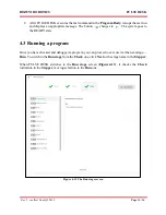
Page 34: ...he system goes to the READY state 4 3 Running a program Once you have checked and debugged a program you can proceed to execute it at the next stage Run To switch to the Run stage from the Check one click Next or the stage name in the Stepper When PULSE DESK switches to the Run stage screen Figure 4 13 it checks the Check indication in the Stepper moving selection to the Run one Figure 4 13 The Ru...

Page 35: ...ning the same program anew and keeps repeating it cyclically until the user stops its execution see Section 4 3 2 4 3 2 Stopping a program To stop a running program click on the Run stage screen After clicking the Stop button changes to the Save Run one In addition PULSE DESK requests to stop program execution when the user selects Load program or New program on the Main Menu see Section 3 2 As th...

Page 36: ...stem will not start causing the red LED on the control box to light up 4 3 3 Saving a program To save a program follow the sequence of actions as below 1 Open the Main menu and select Save program as 2 In the displayed dialogue box Figure 4 15 specify a name for the program and confirm the input by clicking Yes Figure 4 15 Save program as dialog box PULSE DESK saves programs automatically when you...

Page 37: ... stopping the currently executed program by clicking Yes 4 4 2 Deleting a program To delete a program follow the instructions below 1 Load the program you want to delete into the Program Body as described in Section 4 4 1 If the program is already displayed in the Program Body move on to Step 2 2 Open the Main menu and select Delete program PULSE DESK removes the program contents from the Program ...

Page 38: ...net 1 Click the notification Figure 4 16 2 Confirm the update by clicking Yes in the displayed dialog PULSE DESK completes the updating process automatically While updating is under way you will see the green LED on the control box blinking Access to the PULSE DESK user interface is disabled and the LED on the arm is steady green Once updating is over the arm is de energized On the control box the...

Page 39: ...cation see Figure 4 16 5 Click the notification 6 Confirm the update by clicking Yes in the displayed dialog PULSE DESK completes the updating process automatically While updating is under way you will see the green LED on the control box blinking Access to the PULSE DESK user interface is disabled and the LED on the arm is steady green Once updating is over the arm is de energized On the control ...

Page 40: ...utton and select Configure PULSE DESK opens the Configure screen as shown in Figure 5 1 Figure 5 1 Configure screen with the API toggle in the disabled state 3 On the displayed screen switch the Enable Remote API access toggle to the enabled state Disabled state Enabled state 4 Сlick Apply to confirm Now you can start sending API requests and processing API responses For detailed information on av...

Page 41: ...ailable for use as soon as the initialization is over However it is completely isolated from the control box resources and files Operating the sandbox To be able to run and manage custom programs in the sandbox you need to enable SSH access Make sure to use the following connection settings sandbox port 22 control box port 2222 login sandbox default password sandbox IP address DHCP address of the ...

Page 42: ...ograms are cleared from the sandbox To save a program permanently to the sandbox you need to use the Commit command In addition there is a 500 Mb backup folder where you can manually save any data essential to work with the sandbox e g programs execution logs The data in the folder remains intact even when the sandbox is reset to defaults and can be subsequently retrieved at user discretion The de...

Page 43: ...rence only To create a program for your purpose you should use your own values specific to your application and operating conditions Starting PULSE DESK 1 Start PULSE DESK by typing in the dynamic or static IP address of the PULSE arm in the local network for instructions to set IP see Section 2 2 and the port number 8080 in the browser line The browser displays either the starting page of the PUL...

Page 44: ...click the Main Menu button 3 On the Main menu select New program PULSE DESK loads the Edit stage screen of the newly created program with the Wait for command already in the program body 4 On the Main Menu select Save program as and type in a name for your program e g Pick and place nuts in the displayed dialog box ...

Page 45: ...ttons are active in the LEARN mode only When you switch to the PULSE DESK interface to perform any actions e g to edit a point add a command via the Commands menu the mode is off To switch back into the LEARN mode you will have to create a new program In addition we will also add commands to open close the gripper at respective waypoints 6 Press the Free Drive button on the elbow of the robotic ar...

Page 46: ... trajectory The software adds the point to the program body default name Point 1 clearing the Wait for command The Service panel displays Point 1 parameters the coordinates and rotation angles of the tool center point TCP in the position 9 On the arm elbow press the Open gripper button The Open gripper command appears below Point 1 in the program body ...

Page 47: ...he program body On the Service panel you can see the TCP coordinates and rotation angles specifying the arm position at the point 11 To grab nut 1 at Point 2 press the Close gripper button on the arm elbow The corresponding command appears below Point 2 in the program body 12 Set Point 3 to move nut 1 from its original location to a conveyor belt For the purpose repeat the same actions as describe...

Page 48: ... appears below Point 3 in the program body 14 Set Point 4 to pick up nut 2 by following the instructions in Step 6 to 8 15 To grab nut 2 at Point 4 press the Close gripper button on the arm elbow The Close gripper 1 command appears below Point 4 in the program body 16 Set Point 5 to move nut 2 from its original location onto a conveyor belt following the instructions in Step 6 to 8 ...

Page 49: ... of the already preset point in the basic trajectory Point 1 to Point 5 One of the intermediary waypoints is to approach a preset point before lowering the gripper and the other to lift the gripper before moving on to another waypoint 17 Add an intermediary waypoint to approach Point 2 To do this select the command preceding the point in the program body Click In the displayed menu select Point A ...

Page 50: ...lds on the Service panel specify the same coordinates and rotation angles as for Point 6 21 To set intermediary waypoints to approach Point 3 Point 4 and Point 5 repeat the same actions as in Step 17 and Step 18 To specify the waypoint parameters use the same values as for the basic points making sure to change the Z coordinate to a higher value 22 To set intermediary waypoints to lift the gripper...

Page 51: ...o verify and adjust the rest of the points in the program body The Open gripper and Close gripper command have no parameters to edit Adding a comment and setting other commands 27 Click and select Comment PULSE DESK adds the Commentary line to the program body below the currently selected command 28 Drag the command line to the top as shown in the figure below In the Note field on the Service pane...

Page 52: ...n connected to Input 1 on the back panel of the control box 31 In the program body select Point 9 click In the displayed menu select Send to PULSE DESK adds the Send to command to the program body below Point 9 32 In the fields of the Service panel for the Send to command set the output that the arm should use to send a signal to external equipment a conveyor belt as well as the type of the signal...

Page 53: ...conds The value indicates for how long the robotic arm should wait before moving on to execute another command 35 In the program body select Delay click In the displayed menu select Send to PULSE DESK adds the Send to 1 command to the program body below Delay 36 Set the parameters in the Service panel for the Send to 1 command as follows In the Output Type dropdown box select Output 1 In the Value...

Page 54: ...Click PULSE DESK starts executing the specified sequence of commands from first command in the program body and down The bu button changes to You can monitor the test run progress by the way PULSE DESK moves the selection from one command to another When selection is at the Wait for Send to or Delay commands PULSE DESK displays next to Click to skip the commands In case during a test run you find ...

Page 55: ...cute the program If you click Next PULSE DESK displays the Run stage screen Executing and stopping the program 42 On the Run stage screen click Save Run to start execution of the program PULSE DESK executes the sequence of commands in the Program Body Since this pick and place program starts with the Wait for command the arm begins motion only after it receives a proper signal from an external dev...

Page 56: ...on to stop the program execution If you click the Save Run button again after stopping the program PULSE DESK starts executing the program from the very beginning 44 Close the browser window to quit PULSE DESK If you close the browser without stopping the program the robotic arm continues executing it ...

Reviews: