background image

6

MAKING ELECTRICAL CONNECTIONS 

INPUT VOLT.120V

GREEN GROUND

OUTLET BOX 

IN CEILING

GROUND TO 

HANGER BRACKET 

AND DOWNROD

Connect Black(Hot) fan wire to Black outlet wire,
white (Neutral) fan wire to white outlet wire.
Connect green or bare copper wire from outlet 
box to the hanger bracket and downroll ball 
green ground wires together. (Fig.A)

If an additional blue lite kit wire is present, 
then also connect the blue wire to black wire.
Secure all connections with electrical tape.
Make sure there are no loose strands or 
connections.

Follow the steps below to connect the fan 
to your household wiring. Use the wire 
connecting nuts supplied with your fan.

After completing wiring connections, turn all
splices upward and carefully push into outlet 
box.
Separate blue and black wires on one side of 
the outlet box, the white and green wires on 
the other side.

ELECTRICAL CONNECTIONS 

(FOR OPTIONAL WALL CONTROL)

Fig. B & C  illustrate the wiring connections for
optional wall control (The wire color out of wall
control may vary, see wall control’s installation
manual for correct wire connections.)

(Fig.B)

INPUT VOLT.120V

GREEN GROUND

OUTLET BOX 

IN CEILING

GROUND TO 

HANGER BRACKET 

AND DOWNROD

BLK

BLK

BLK

BLUE

BLUE

WH

WH

WH

WH

GRN

FAN

LIGHT

(Fig.A)

Follow this wiring diagram. Fan & Wall control 
sold separately, choose wall dimming control 
compatible with LED light only.

LIGHT

SWITCH

BLK

BLUE

BLUE

BLK

BLK

WH

WH

FAN

LIGHT

WH

WH

Step 1.

Warning: 

All wiring must be in accordance with 

national and local electrical codes ANSI/NFPA
70. If you are unfamiliar with wiring or in doubt,
consult a qualified electrician.

Step 2.

Summary of Contents for 1072-PC

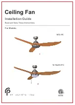
Page 1: ...Installation Guide For Models 1072 PC 1072LED PC...

Page 2: ...LS REQUIRED 2 3 INSTALLING MOUNTING BRACKET 4 DOWNROD BALL ASSEMBLY 5 HANGING THE FAN MOTOR ASSEMBLY 5 6 7 BLADE INSTALLATION 7 8 12 11 13 9 OPERATING YOUR FAN ATTACHING SWITCH HOUSING COVER 10 CANOPY...

Page 3: ...to the outlet box 7 After completing installation check all setscrews and make sure they are firmly secured WARNING To reduce the risk of fire or electric shock do NOT use this fan with any solid sta...

Page 4: ...4 5 6 7 Fan blades 3 1 5 6 7 8 2 3 4 Wire nuts 3 Quantity a Wood screws 2 b Flat washers 2 c Hanging bracket screws 2 d Spring washers 2 e Blade screws and flat washers 10 f g Pull chain Wood tassel...

Page 5: ...ED light kit 1 Quantity 1 2 3 4 5 6 7 Fan blades 3 1 5 6 7 8 2 3 4 Model 1072LED PC Wire nuts 3 Quantity a Wood screws 2 b Flat washers 2 c Hanging bracket screws 2 d Spring washers 2 e Blade screws a...

Page 6: ...ng washers If not mount to ceiling outlet box use wood screws and flat washers and mount securely to ceiling beam Note Do not mount directly to sheet rock or ceiling tiles The ceiling fan must be inst...

Page 7: ...rts Insert fan wires and safety cable through downrod Thread downrod into top of fan motor housing until holes for downrod pin align with holes in collar Make sure wires do not get twisted Insert down...

Page 8: ...lices upward and carefully push into outlet box Separate blue and black wires on one side of the outlet box the white and green wires on the other side ELECTRICAL CONNECTIONS FOR OPTIONAL WALL CONTROL...

Page 9: ...nto the slotted holes in canopy and tighten firmly Loosen but not remove NOTE Only use an optional wall switch designed for use with ceiling fans If you select to control the motor from a wall switch...

Page 10: ...screws through the slot hole NOTE Place the fan blade on the flywheel and align the middle hole on the fan blade with the hole next to a debossed line on the flywheel Repeat this process to install t...

Page 11: ...9 Model 1072 PC ATTACHING SWITCH HOUSING COVER Locate 3 screws on switch housing mounting plate attach the cover to switch housing by using these 3 screws and tighten securely Switch housing...

Page 12: ...ct the 4 pin connector from the LED light kit to the 4 pin connector from motor assembly together carefully The LED light kit is designed for this specific application on ceiling fan model 1072LED PC...

Page 13: ...inimum of 7 feet clearance from the trailing edge of the blades to the floor be careful to avoid raising your arms or nay object in the path of the blades Connect the two WOOD TASSELS to the pull chai...

Page 14: ...nticlockwise direction The airflow will be directed downwards for cooling in summer WINTER Mode The reverse switch shall be in the right WINTER position to make the fan rotate in a clockwise direction...

Page 15: ...witch wire connections in the switch housing Make sure all motor housing screws are snug Make sure the screws that attach the fan blade bracket to the motor hub is tight Make sure wire nut connections...

Page 16: ...RP 120419...

Reviews: