
OPERATION MANUAL
IBS 40002206
Page | 11
V1 (January 2017)
Installation
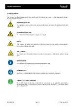
WARNING
Installation of these units should be carried out by appropriately qualified and skilled
personnel. Failure to do so may invalidate the warranty.
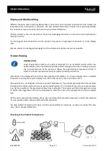
The equipment will be delivered to site boxed on a pallet.
Remove all packaging materials from the unit and dispose of correctly, in accordance with local regulations.
Care must be taken when removing packaging so not to damage or scratch the painted, glass or stainless
steel surfaces.
Remove all temporary tape.
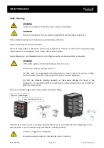
Prior to the first use, clean with a proprietary cleaning solution, following the manufacturers’ instructions.
Refer to the cleaning and maintenance section of this document. Ensure excessive water is not used. Do
NOT use aggressive detergents.
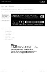
If there are any signs of damage, contact
RPI Industries, Inc.
immediately. Failure to report faults,
defects or missing items upon delivery may incur charges. Deliveries must only be signed off if they are in a
satisfactory condition.
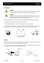
Ensure safe manual handling practices are employed at all times. The unit should be lifted into
position using the correct lifting procedures, in line with local and regional safety policies.
The following considerations must be given to the site of installation:
AVOID placing sources of heat near the appliance.
Do NOT install the appliance near other equipment that generates high temperatures in order to
avoid damage.
The equipment should be sited so that it is not affected by draughts from doors or air conditioning
systems. Temperature fluctuations are likely to occur if the equipment is not sited appropriately. This
will have an adverse effect on product temperatures and may increase running costs.
Ensure the floor supports the weight of the unit at full capacity.
Ensure the unit is installed on a flat, even surface.
The supporting or surrounding surfaces for the appliance must be:
Non-combustible;
Level, flat and even;
Able to support the appliance’s weight at full load, without undergoing deformation or structural
failure;
Immovable.