background image

19

Summary of Contents for 2010446

Page 1: ...Quick Start Guide RSST 2000 Series Stock number 2010446 2010448 2010449 2010450 EN rspro com ...

Page 2: ...re limited to the above RS PRO shall not be liable for loss of use of the instrument or other incidental or consequential damages expenses or economic loss or for any claim or claims for such damage expense or economic loss Some states or countries laws vary so the above limitations or exclusions may not apply to you For full terms and conditions refer to the RS PRO website This quick start guide ...

Page 3: ...ls may appear in the user manual or on the instrument Warning Warning Identifies conditions or practices that could result in injury or loss of life Caution Caution Identifies conditions or practices that could result in damage to the instrument or to other properties DANGER High Voltage Attention Refer to the Manual Do not dispose electronic equipment as unsorted municipal waste Please use a sepa...

Page 4: ...d to the terminal which is marked with the letter N or coloured Blue or Black The wire which is coloured Brown must be connected to the terminal marked with the letter L or P or coloured Brown or Red If in doubt consult the instructions provided with the equipment or contact the supplier This cable appliance should be protected by a suitably rated and approved HBC mains fuse refer to the rating in...

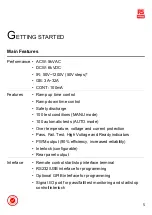
Page 5: ...omatic tests AUTO mode Over temperature voltage and current protection Pass Fail Test High Voltage and Ready indicators PWM output 90 efficiency increased reliability Interlock configurable Rear panel output Interface Remote control start stop interface terminal RS232 USB interface for programming Optional GPIB interface for programming Signal I O port for pass fail test monitoring and start stop ...

Page 6: ...t Function Keys Green Zone 5 Display 6 Soft Keys Blue Zone 7 PASS FAIL Indicators 8 Scroll Wheel 9 HIGH VOLTAGE Indicator 10 HIGH VOLTAGE Output Terminal 11 SENSE L RETURN Terminal 12 SENSE H Output Terminal 13 SOURCE L RSST 2004 only 14 SOURCE H RSST 2004 only 15 REMOTE Terminal 16 USB A Type Host Port 17 Mode Keys AUTO MANUAL SYSTEM in Red Zone ...

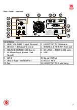
Page 7: ...put Terminal 2 HIGH VOLTAGE Indicator 3 SENSE H Output Terminal 4 SENSE L RETURN Terminal 5 SOURCE H RSST 2004 only 6 SOURCE L RSST 2004 only 7 AC Mains Input Power Cord Socket 8 GND 9 GPIB 10 Signal I O Port 11 USB B Type Interface Port 12 RS 232 Port 13 Fan 14 HIGH VOLTAGE pilot lamp ...

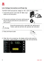
Page 8: ...anel 2 If the power cord does not have an earth ground ensure the ground terminal is connected to an earth ground Warning Ensure the power cord is connected to an earth ground Failure could be harmful to the operator and instrument 3 Press the Power button 4 When the unit is powered up the display will show the last time parameters in either MANU or AUTO test mode as shown below ...

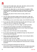
Page 9: ... clearly labeled with appropriate warning signage 3 The operator should not wear any conductive materials jewelry badges or other items such wrist watches 4 The operator should wear insulation gloves for high voltage protection 5 Ensure the earth ground of the line voltage is properly grounded 6 Ensure any devices that are adversely affected by magnetic fields are not placed near the tester Operat...

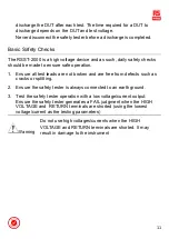
Page 10: ...ld charge the chassis to dangerously high voltages 5 Ensure the earth ground of the line voltage is properly grounded 6 Only connect the test leads to the HIGH VOLTAGE SOURCE H SENSE H terminals before the start of a test Keep the test leads disconnected at all other times 7 Always press the STOP button when pausing testing 8 Do not leave the safety tester unattended Always turn the power off when...

Page 11: ...all test leads are not broken and are free from defects such as cracks or splitting 2 Ensure the safety tester is always connected to an earth ground 3 Test the safety tester operation with a low voltage current output Ensure the safety tester generates a FAIL judgment when the HIGH VOLTAGE and RETURN terminals are shorted using the lowest voltage current as the testing parameters Warning Do not u...

Page 12: ... Output Voltage Range 0 050kV 5 000kV1 Output Voltage Resolution 1V Output Voltage Accuracy 1 of setting 5V with no load Maximum Rated Load1 200 VA 5kV 40mA Maximum Rated Current 40mA 0 001mA 10mA 0 1kV V 0 5kV 0 001mA 40mA 0 5kV V 5kV Output Voltage Waveform Sine wave Frequency 50 Hz 60 Hz Voltage Regulation 1 5V Maximum rated load no load Voltmeter Accuracy 1 of reading 5V Current Measurement Ra...

Page 13: ...urrent is set below 30mA DC Withstanding Voltage Output Voltage Range 0 050kV 6 000kV1 Output Voltage Resolution 1V Output Voltage Accuracy 1 of setting 5V with no load Maximum Rated Load 50W 5kV 10mA Maximum Rated Current 10mA 0 001mA 2mA 0 05kV V 0 5kV 0 001mA 10mA 0 5kV V 6kV Voltmeter Accuracy 1 of reading 5V Voltage Regulation 1 5V Maximum rated load no load Current Measurement Range 0 001mA ...

Page 14: ...ance Test Output Voltage 50V 1200V Output Voltage Resolution 50V Output Voltage Accuracy 1 of setting 5V with no load Resistance Measurement Range 1MΩ 50MΩ Test Voltage Measurement Range Accuracy 50V V 450V 0 1MΩ 1MΩ 5 of reading 3 count 1MΩ 50MΩ 5 of reading 1 count 51MΩ 2GΩ 10 of reading 1 count 500V V 1200V 0 1MΩ 50MΩ 5 of reading 3 count 1MΩ 500MΩ 5 of reading 1 count 501MΩ 9 999GΩ 10 of readi...

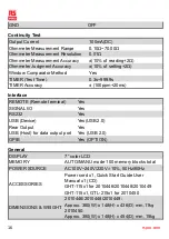
Page 15: ... from 0 5 second Ground Bond Test Output Current Range 3 00A 32 00A Output Current Accuracy 1 of setting 0 2A when 3A I 8A 1 of setting 0 05A when 8A I 32A Output Current Resolution 0 01A Frequency 50Hz 60Hz selectable Test Voltage Approximately max 8VAC open circuit Ohmmeter Measurement Range 1mΩ 650mΩ Ohmmeter Measurement Resolution 0 1m Ohmmeter Measurement Accuracy 1 of reading 2m Ohmmeter Jud...

Page 16: ...e REMOTE Remote terminal Yes SIGNAL I O Yes RS232 Yes USB Device Yes USB 2 0 Rear Output Yes USB Host for data output port Yes USB 2 0 GPIB Yes OPTION General DISPLAY 7 color LCD MEMORY AUTO MANU mode 100 memory blocks total POWER SOURCE AC100V 240V 230V 10 50Hz 60Hz ACCESSORIES Power cord x1 Quick Start Guide User Manual x1 CD GHT 115x1 for 2010446 2010448 2010449 GHT 115x1 GTL 215x1 for 2010450 ...

Page 17: ...ent control and laboratory use EMC requirements 2013 Conducted Radiated Emission EN 55011 2016 A1 2017 Calss A Electrical Fast Transients EN 61000 4 4 2012 Current Harmonics EN 61000 3 2 2014 Surge Immunity EN 61000 4 5 2014 Voltage Fluctuations EN 61000 3 3 2013 Conducted Susceptibility EN 61000 4 6 2014 Electrostatic Discharge EN 61000 4 2 2009 Power Frequency Magnetic Field EN 61000 4 8 2010 Ra...

Page 18: ...East Sea Business Centre Phase 2 NO 618 Yan an Eastern Road Shanghai 200001 China Europe RS Components Ltd PO Box 99 Corby Northants NN17 9RS United Kingdom Japan RS Components Ltd West Tower 12th Floor Yokohama Business Park 134 Godocho Hodogaya Yokohama Kanagawa 240 0005 Japan North America Allied Electronics 7151 Jack Newell Blvd S Fort Worth Texas 76118 U S A South America RS Componentes Elect...

Page 19: ...19 ...

Reviews: