background image


File No.


 VersionA1 

2

Internal 

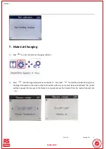
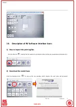
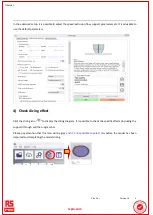
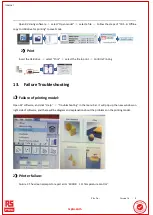
10. Description of RV Software Interface Icons

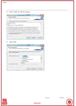
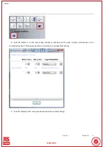
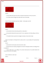
1) How to import the printing files

  Click the file icon 

, identify the file needs to be printed and sliced in the pop-up window and double click. 

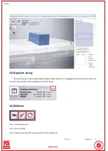
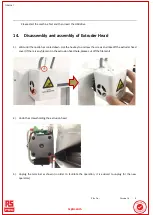
2) Download the model base

Click the download icon 

 ”

  to pop up the new window, which requires the user name and password.

rrsp

sprro.c

o.com

om

Summary of Contents for 202-7268

Page 1: ...File No VersionA1 1 Internal High Speed 3D Printer ENGLISH rspro com ...

Page 2: ... place this machine in a well ventilated and clean environment Please don t place this machine an environment that is subject to large vibrations or other unstable elements the vibration or movement of the machine will affect the print quality Please only use the supplied power cords and power supply with this machine Use of any other leads or power supply will result in damage to the machine Plea...

Page 3: ... use may result in injury This Manual is protected by copyright and this Company shall reserve the final interpretation right Without the authorization This Company has the rights to alter the content relating to this type of printer and in its operation manual without the prior separate notification r rsp spr ro c o com om ...

Page 4: ...ameter Software parameter Type High Speed 3D Printer Slicing software REALvision Quantity of Nozzle 1 Slicing file format STL Diameter of Nozzle 0 4mm Printing format fcode Printing page thickness 0 1mm 0 4mm Computer operation system Windows XP Vista 7 8 10 r rsp spr ro c o com om ...

Page 5: ...nt 100 240VAC 50 60Hz 4 0A Advisory temperature of nozzle 220 Operating voltage current 20V 11A Advisory platform temperature 60 75 Output power Max 220W Diameter of consumables 1 75mm Molding dimension 150 x 150 x 140 mm Product dimension 355 L 267 W 410 H mm Molding technology FDM Fused Deposition Modeling Packing dimension 496 L 376 W 356 H mm Power off continuous printing Support Net weight 8k...

Page 6: ... Magnetic printing platform A 1 3 External fan 1 11 Cutting nippers 1 4 USB flash drive 1 12 Screws 2 5 Filament Tube 1 13 Spool holder 1 6 Hex key 1 14 Tweezers 1 7 HS Filament 1 15 AR identification sticker 1 8 Five Quick Guides German Engl ish French Ita lian Spanish 5 r rsp spr ro c o com om ...

Page 7: ...spool holder in the position shown below and then replace the screws tighten the screws until the holder is held securely c Install the external fan 1 Unscrew the upper two screws on the right side with the hex key provided place the fan in position as shown below replace the screws and tighten until the fan is held securely 2 Connect the fan to the printer using the lead as shown below 3 Adjust t...

Page 8: ... in the black ring on right side as shown leave the other end free e Installing the print bed Place the bed on the printer as shown below Use the 4 provided bull clips to secure the bed to the printer taking care to ensure that the platform and bed are clear of obstacles r rsp spr ro c o com om ...

Page 9: ...t up interface Select this option to enter the printing interface where it is possible select the file that is to be printed and confirm Select this option to enter the material changing interface set the temperature to 220 and click Once the temperature reached the required temperature follow the prompts given Select this option to enter the XYZ axis and extruder moving interface Select this opti...

Page 10: ...pts for further operation 3 Moving interface Home button The Home button will move the print bed and the extruder to the start home position The right and left arrows are used to move the extruder the up and down arrows are used to move the print bed front to back This option is used to move the print bed up or down The up and down arrows are used to move the print bed This option is used to move ...

Page 11: ...ase After the required temperature is reached press the back arrow then perform the feeding and retreating operation to the extruder head as listed above 4 Set up interface Select this option to enter the platform calibration interface Select this option to enter the language set up interface Select this option to enter the version information and firmware upgrading interface 4 1 Platform calibrat...

Page 12: ...ge is selected Left facing arrow is used to return to the previous menu 4 3 Version information and firmware upgrading interface This screen gives the software and firmware information This option is to be used when there is a software upgrade available and the printer requires upgrading Left facing arrow is used to return to the previous menu 6 Calibration Platform 1 Enter the platform calibratio...

Page 13: ...n then press the next button to move onto the next step 3 Use the up down arrows on the screen to adjust the gap between the print bed and the nozzle leaving a 1mm gap When finished press the next button to move onto the next step 4 The printer will automatically return to the start position Move to the next step after completing r rsp spr ro c o com om ...

Page 14: ...p Adjust the points 2 and 3 by using the above method The figure below shows the locations of the three leveling points After completing the above adjustments it is advised that this procedure is repeated to ensure the bed is level Click the return arrow twice the extruder will return to the first position ready to start again Use the A4 paper to check whether points 1 to 3 have the same resistanc...

Page 15: ...e target temperature reaches 215 then click to start the extruder heating Once the target temperature has been reached the printer will carry out several steps automatically The printer will then request the removal of the filament manually remove the filament from the nozzle hole and click r rsp spr ro c o com om ...

Page 16: ...step 7 and automatically go to step 8 4 Insert the filament into the feeding hole as shown in the first image below click when the filament comes out of the nozzle as shown in the second image below This will complete the filament change procedure 8 Feeding 1 Click to enter the moving interface Then click the temperature icon to enter the temperature rising interface r rsp spr ro c o com om ...

Page 17: ...f extruder head as shown in the steps above On the printer navigate to the movement interface press the downward arrow below the nozzle symbol on the screen until the filament starts to extrude from the nozzle Attention If the filament that comes out from extruder head is not long enough please keep pressing the feed button ensuring there is enough filament left to pull the filament out if require...

Page 18: ...erature of the extruder if the temperature drops below the melt point of the filament the filament will get stuck in the extruder After returning to the movement interface feed the filament immediately as the temperature will start to reduce if the printer is left to idle r rsp spr ro c o com om ...

Page 19: ...Identify REALvision_Setup installation package in the delivered USB drive and double click the icon to open 2 Select the required installation language in the new pop up window and then click OK to enter the next step 3 Select Next r rsp spr ro c o com om ...

Page 20: ...File No VersionA1 2 Internal 4 Select I Agree to enter the next step 5 Select Next r rsp spr ro c o com om ...

Page 21: ...llation location click Next If it is required to install to a different location please click the Browse button navigate to the selected location and click the Next button after the installation location is selected 7 Select Install r rsp spr ro c o com om ...

Page 22: ...File No VersionA1 2 Internal 8 When the pop up prompt window asks Whether activate software now select Yes YES NO r rsp spr ro c o com om ...

Page 23: ...onA1 2 Internal 9 Select Retype your product key 10 Open the Code text in the installation program file copy the activation code and paste in the Product Key box and then click the Next Step r rsp spr ro c o com om ...

Page 24: ...ivation is successful and click Complete 12 Click Finish the software installation is now complete There will be a prompt about updating when opening for the first time select Yes to update and select No to not update temporarily r rsp spr ro c o com om ...

Page 25: ...ow to import the printing files Click the file icon identify the file needs to be printed and sliced in the pop up window and double click 2 Download the model base Click the download icon to pop up the new window which requires the user name and password r rsp spr ro c o com om ...

Page 26: ... adjust the layer thickness filling rate shell thickness print temperature print bed temperature language etc It is advisable to use the recommended setup in the beginning If any parameters have been adjusted please click OK for the changes to take effect after completing the adjustments r rsp spr ro c o com om ...

Page 27: ...arameters 4 Check slicing effect Click the slicing icon to display the slicing diagram It is possible to check the specific effects including the support through pull the progress bar Please pay attention that this icon will be grey and it s not possible to select this before the model has been imported and completing the model slicing r rsp spr ro c o com om ...

Page 28: ...Connect the printer to the computer with USB cable select the serial port to be connected in the Print Window Description of icon series label Label 1 is the series port select the series port after connecting to the computer Label 2 is the temperature rising the temperature starts to rise after clicking Label 3 is print it starts to print after clicking Label 4 is XY reset it starts to reset the ...

Page 29: ...orm and extrusion head Label 10 is the disconnection it possible disconnect after clicking Start to Print Label 11 is for canceling operation it is possible cancel the current any working status after clicking Attention After the printer is connected to the computer it is necessary to click the reset Above Label 4 to confirm if the connection is working The operation can only be continued once the...

Page 30: ...le to start printing Once the printing is complete wait for the print bed to cool down before removing the print from the print bed 6 Model moving Special description of using mouse Left button has different functions according to the different situations Right button rotate the platform in 360 Central wheel Zoom in and zoom out the platform Click the direction icon to adjust the X Y values below ...

Page 31: ...hold down the left mouse button and then move the mouse for zooming Please note that the fixed length and width ratio with below If removing and changing X or Y or Z it is possible to be only effective to X Y Z to be changed Reset and return to the parameters before being changed 8 Rotation Model rotates on Z plane axis Click the rotation icon and input the required angle in the box below to chang...

Page 32: ...he icon then click the corresponding axis which is to be mirrored 10 Support Click the icon to decide whether to add support and which type of support according to the model type 11 Copy Click the icon to complete the copy r rsp spr ro c o com om ...

Page 33: ... click Yes 13 Model merging After importing 2 or more models select Edit select all Models from the menu bar or select all models directly by using the keyboard Ctrl A and click the icon to complete the merge 14 Customize the printing layer 1 Click the icon and pop up a new settings window r rsp spr ro c o com om ...

Page 34: ... the new setting window to add layer set the slice number and thickness in the corresponding box at the beginning and end and close the window after setting 3 Click the Display Slice icon to preview the thickness of the Settings r rsp spr ro c o com om ...

Page 35: ...atically by default when imported It is suggested to switch this off and to only slice once the model has been adjusted then start slicing 16 REALview Icon 1 Reset the camera Icon 2 Start and End Icon 3 Reset the model after being adjusted in the model area r rsp spr ro c o com om ...

Page 36: ...e RV software and select Help REALview Help Load REALview Focus into the workspace from the menu bar or directly import the AR prop file from the USB flash drive 2 After importing the model on the USB drive use 3D printer to print out 3 Stick the AR identification sticker on the item to be printed r rsp spr ro c o com om ...

Page 37: ...om of software to start 5 Point the item against camera with the distance of about 25CM Move the item and observe the model on screen and the model will be changed along with turning the item 6 Click the icon to stop 12 First print 1 Slice r rsp spr ro c o com om ...

Page 38: ...ect the file to print Confirm Printing 13 Failure Troubleshooting 1 Failure of printing model Open RV software and click Help Troubleshooting in the menu bar It will pop up the new window on right side of software and there will be diagram and explanation about the problems on the printing model 2 Printer failure Failure 1 The screen prompts to report error ERROR 111 Temperature Control r rsp spr ...

Page 39: ...fter dissembling and then re install it C The platform thermocouple has been damaged and replace with new thermocouple Failure 3 The filament is not flowing from the nozzle and the is a noise sounding like Deng Deng Deng Blockage Solution A Check whether the temperature of extrusion head is normal B Check the clearance between printing platform and nozzle it will appear that there is a blockage if...

Page 40: ...zle has cooled down Use the hex key to unscrew the screws and take off the extruder head cover If there is any filament in the extrusion head hole please cut off the filament 2 Undo the screws holding the extrusion head 3 Unplug the terminal as shown In order to facilitate the operation it is advised to unplug for the new operators r rsp spr ro c o com om ...

Page 41: ...ove the screws connected to the fan remove the fan and pay attention to protecting the fan cables 5 Remove the screws on both sides 6 Check whether there is any broken materials or other crushed materials inside r rsp spr ro c o com om ...

Page 42: ...g the extrusion head to power cable Poke the filament in tube with tools to enable the filament to be squeezed out from the nozzle Please pay attention to the high temperature scalding in this procedure 8 Cover up the feeding block please note that the small shaft in the middle can t be dropped out r rsp spr ro c o com om ...

Page 43: ...the cooling fin and tighten with screws Please note that the cooling fin needs to be in the right position when twisting the screws prior to tightening as below diagram 10 Install the fan 11 Plug the terminal on cable r rsp spr ro c o com om ...

Page 44: ...File No VersionA1 4 Internal 12 Install the extrusion and tighten with screws 13 Install the extrusion head cover and tighten with screws r rsp spr ro c o com om ...

Page 45: ...File No VersionA1 4 Internal r rsp spr ro c o com om ...

Reviews: