11
12
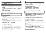
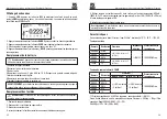
AC 3000A Current ( with Current Transducer ) measurement
Maximum input AC/DC current is 3000A (input VHz%CAPTemp Ω
) . Do not
measure currents exceeding the limits given in this manual.
1. Select positions
2. Insert the Current Transducer red cable into input terminal
V Hz% CAP Temp
and the black cable into input terminal COM.
3. Position the red lead and the black lead respectively in the spots of the circuit to be
measured (see). The display shows the value of voltage.
4. Select current Transducer Rang.
5. Press the RANG key to select“30A. 300A. 3000A”, when pressing the RANGE button, the
meter shall display the range selected for 2sec.(before start measuring)
6. To use the HOLD, MAX MIN, and REL functions.
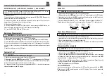
Resistance Measurements
WARNING
: Never test resistance on a live circuit.
1. Set the rotary function switch to the Ω
CAP position.
2. Momentarily press the
MODE
button until the Ω
symbol appears on the LCD display.
3. Insert the black test lead into the COM input jack and the red test lead into the Ω input jack.
4. Touch the test lead probes to the component under test. If the component is installed in
a circuit, it is best to disconnect one side before testing to eliminate interference with other
devices.
5. Read the resistance in on the LCD display.
Continuity Test
WARNING
: Never test continuity on a live circuit.
1. Set the rotary function switch to the Ω
CAP position.
2. Momentarily press the
MODE
button until the “
” symbol appears on the LCD display.
3. Insert the black test lead into the COM input jack and the red test lead into the Ω input jack.
4. Touch the test lead probes to the device or wire under test.
5. A beeper will sound if the resistance is approximately 50Ω or less and the resistance
value will be shown on the LCD display.
Professional True RMS Digital Multimeter/ English
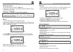
Diode Test
WARNING
: Never test diodes in a live circuit.
1. Set the rotary function switch to the Ω
CAP position.
2. Momentarily press the
MODE
button until the “ “ symbol appears on the LCD display.
3. Insert the black test lead into the
COM
input jack and the red test lead into the Ω input jack.
4. Touch the test lead probes to the diode under test.
5. Forward voltage will indicate 0.4 to 0.7 on the display. Reverse voltage will indicate “OL”.
Shorted devices will indicate near 0 and an open device will indicate “OL” in both polarities.
Capacitance Measurements
WARNING
: Safely discharge capacitors before taking capacitance measurements.
1. Set the rotary function switch to the Ω
CAP position.
2. Insert the black test lead into the COM input jack and the red test lead into the input jack.
3. Touch the test lead probes to the capacitor under test.
4. Read the capacitance value on the LCD display. It may take up to a minute to get a stable
reading on large capacitors.
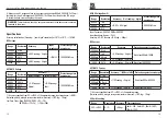
Temperature Measurements
WARNING
: Do not touch the temperature probe to live circuits.
1. Set the rotary function switch to the
TEMP°F °C
position.
2. Momentarily press the
MODE
button to select readings in °F or °C.
3. Connect the Temperature Probe to the Banana Plug Adapter. Note the – and + markings
on the adapter. Connect the adapter to the meter, making sure the – side goes into the
COM
input jack and the + side goes into the
°F °C
input jack.
4. Touch the tip of the Temperature Probe to the object being measured. Keeps the probe
touching the object until the reading stabilizes (about 30 sec).
5. Read the temperature on the LCD display.
Turn on Bluetooth
Leave the rotating function switch away from the OFF position. press and hold the
MODE
button until the “ ” symbol appears on the LCD display. Then it can be paired and
communicated with APP.
Professional True RMS Digital Multimeter/ English
Summary of Contents for 204-8305
Page 48: ......


