background image


GETTING STARTED


17/11/2016 Version No. 002 

19


Display Overview 

Primary Display

Secondary Display

Function status icons

Secondary 

measurement units

Primary measurement units

Primary measurement

function icons

Secondary 

measurement 
function icons

REAR

GPIB

USB

LAN

RS232

FILT

RCL

STO

COMP

2ND

dBm

EXT

SHIFT

ERR

LIMIT

AUTOMATH

4W

2W

DC

AC

A

V

m

m

Hz

W

k

M

W

S

F

C

m

dB

%

A

V

m

m

Hz

W

k

M

W

S

F

C

RMT

MAX

MIN

REL

HOLD

S

M

F

AUTO

4W

2W

DC

AC

USBSTO n

μF

MEM

RATIO UNCAL

μ F

120000  Counts  Dual  Measurement  Multimeter

-


Primary Measurement 

Function Icons 

Displays the primary measurement function. 

Primary Measurement 

Units 

Displays the units for the primary measurement function. 

Secondary Display 

Displays the results of the secondary measurement. 

Secondary 

Measurement Units 

Displays the units for the secondary measurement 

function. 

Secondary 

Measurement function 

icons  

Displays the secondary measurement function. 

Function Status Icons  Display status icons for operations/functions that are not 

linked to the primary or secondary functions. 

Primary Display 

Displays the results of the primary measurement. 

Summary of Contents for IDM-8351

Page 1: ...Instruction Manual IDM 8351 Dual Measurement Multimeter EN FR DE IT SP...

Page 2: ......

Page 3: ...37 Resistance Measurement 41 Diode Test 44 Capacitance Measurement 45 Continuity Test 47 Frequency Period Measurement 50 Temperature Measurement 53 Dual Measurement Overview 57 Advanced Measurement O...

Page 4: ...ITAL I O 90 Digital I O Overview 91 REMOTE CONTROL 95 Configure Remote Control Interface 96 Return to Local Control 100 COMMAND OVERVIEW 101 Command Syntax 101 Command List 106 FAQ 152 APPENDIX 154 Sy...

Page 5: ...ep the instrument in the best possible condition Safety Symbols These safety symbols may appear in this manual or on the instrument WARNING Warning Identifies conditions or practices that could result...

Page 6: ...any heavy object on the instrument Avoid severe impact or rough handling that can lead to damaging the instrument Do not discharge static electricity to the instrument Use only mating connectors not...

Page 7: ...circuits directly connected to the low voltage installation Power Supply WARNING AC Input voltage 100 120 220 240 V AC 50 60Hz The power supply voltage should not fluctuate more than 10 Connect the pr...

Page 8: ...50 RH non condensing Altitude 2000m Note EN 61010 1 2010 specifies the pollution degrees and their requirements as follows The IDM 8351 falls under degree 2 Pollution refers to addition of foreign ma...

Page 9: ...erature nor humidity is controlled Storage environment Location Indoor Temperature 40 C to 70 C Humidity 90 RH non condensing Disposal Do not dispose this instrument as unsorted municipal waste Please...

Page 10: ...Blue must be connected to the terminal which is marked with the letter N or coloured Blue or Black The wire which is coloured Brown must be connected to the terminal marked with the letter L or P or...

Page 11: ...multimeter in a nutshell including accessories package contents its main features and front rear panel introduction Characteristics 10 Accessories 11 Appearance 12 IDM 8351 Front Panel 12 Display Ove...

Page 12: ...racy 0 012 High current range 10A High Voltage range 1000V High ACV frequency response 100kHz Features The fastest sampling rate is 320 Readings sec for ADC and PC transmission The diode test open cir...

Page 13: ...ly controlled Only one function at a time can be used Software Excel Addins LABVIEW driver Accessories Standard Accessories Part number Description 82DMx83510E x1 CD ROM User Manual Software Driver 82...

Page 14: ...V W Auto DC AC TEMP SENSE W 4W COM 200Vpk H I LO 10A 1A CAT II 600V dBm Function keys Sense LO Terminal Power Switch Main Display DC AC 1A Terminal 1 25A 1000V Fuse Holder COM Terminal Arrow keys DC A...

Page 15: ...1A CAT II 600V Accepts ground COM line in all measurements The maximum withstand voltage between this terminal and earth is 500Vpk DC AC 1A Terminal AMPS Fuse Holder 1000V 750V 500Vpk INPUT FUSE 1 25...

Page 16: ...ccepts HI sense line in 4W resistance measurement Sense LO Terminal Accepts LO sense line in 4W resistance measurement Measurement Keys The top row of measurement keys are used for basic DMM measureme...

Page 17: ...C current page 37 2W 4W 2W 4W TEMP Measures resistance 2W or 4W See page 41 TEMP SHIFT 2W 4W SHIFT EXIT 2W 4W TEMP Measures temperature See page 53 Measures diodes or continuity depending on the selec...

Page 18: ...EL Measures the Relative value page 67 REL SHIFT REL SHIFT EXIT REL REL Manually sets the reference value for the Relative value measurement MX MN MX MN MATH Measures the Maximum or the Minimum value...

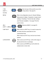
Page 19: ...acter settings and Firmware installation See page 76 for the system menu dBm SHIFT MENU SHIFT EXIT MENU dBm Measures dBm W see page 63 SHIFT EXIT SHIFT EXIT When used as a SHIFT key it is used to acce...

Page 20: ...ANGE The arrow keys are used to navigate the menu system and edit values The Up and Down arrow keys will also manually set the range for the voltage and current measurements The Left and Right arrow k...

Page 21: ...EM RATIO UNCAL n F 120000 Counts Dual Measurement Multimeter Primary Measurement Function Icons Displays the primary measurement function Primary Measurement Units Displays the units for the primary m...

Page 22: ...NG DIGITAL I O RS232 H F L F PASS EOM SET3 SET2 SET1 SET4 TRIG IN GND Fuse 0 125AT 0 063AT Digital I O Port DIGITAL I O H F L F PASS EOM SET3 SET2 SET1 SET4 TRIG IN GND The Digital I O port is used fo...

Page 23: ...GETTING STARTED 17 11 2016 Version No 002 21 RS232 RS232 RS232 port This port is used for remote control See page 96 USB Device Port Type B USB port This port is used for remote control See page 96...

Page 24: ...lish 22 17 11 2016 Version No 002 Set Up Tilting the Stand From the base of the handle gently pull the handle out sideways and then rotate it to one of the following positions Horizontal position Tilt...

Page 25: ...und connector on the power cord is connected to a safety ground This will influence the measurement accuracy 3 Push to turn on the main power switch on the front panel 4 The display turns on and shows...

Page 26: ...For example To activate the DCV function press the DCV key DCV DCI To activate a secondary function first press the SHIFT key followed by the function key for the secondary function For example To ac...

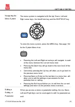
Page 27: ...on the current menu level Pressing the Down key will go down to the next level of the menu tree Conversely pressing the Up key will allow you to go back to the previous menu level Pressing Down or Ent...

Page 28: ...RANGE RANGE If a setting or parameter is flashing it indicates that that particular parameter can be edited Pressing the Left or Right arrow key will allow you to select a digit or character to edit...

Page 29: ...5 AC DC Current Measurement 37 Select the Current Range 38 Resistance Measurement 41 Select the Resistance Range 42 Diode Test 44 Capacitance Measurement 45 Select the Capacitance Range 46 Continuity...

Page 30: ...Measurement Overview 62 Supported Advanced Measurement Functions 62 dBm dB W Measurement 63 dBm dB Calculation 63 Measuring dBm W 63 Measure dB 65 Max Min Measurement 66 Relative Measurement 67 Hold...

Page 31: ...ccuracy Consider these tradeoffs when selecting the refresh rate For further details please see the specifications Refresh rate Reading S Function S M F Continuity Diode 10 40 320 DCV DCI 10 40 320 AC...

Page 32: ...ate setting V Automatic Manual Triggering Overview By default the IDM 8351 automatically triggers according to the refresh rate See the previous page for refresh rate setting details The TRIG IN pin o...

Page 33: ...voltage press the ACV and DCV keys at the same time 2 The mode will switch to AC DC or AC DC mode immediately as shown below REAR GPIB CV CC SWEEP FILT RCL STO COMP 2ND dBm EXT SHIFT ERR LIMIT AUTO MA...

Page 34: ...n be set automatically or manually Auto Range To turn the automatic range selection On Off press the AUTO key Manual Range Press the Up or the Down key to select the range The AUTO indicator turns Off...

Page 35: ...e dynamic range for the selected DC range Any voltage exceeding the dynamic range will be clipped at the upper lower range limit Under these conditions the range that is chosen with the Auto range fun...

Page 36: ...tude of the AC component in the measured signal is higher or lower than the dynamic range of the range being currently selected by the auto range function Maximum DCV Dynamic Range Selected DCV Range...

Page 37: ...e 2 000 1 000 0 000 Rectified Square 1 414 0 707 0 707 Rectangular Pulse 2 000 2K K 2 D D D X Y 2D D X Y Triangle Sawtooth 3 464 1 000 0 000 Crest Factor Table Background Crest factor is the ratio of...

Page 38: ...dynamic range limitations at full scale If the crest factor is more than 3 0 it usually indicates an abnormal waveform as seen from the below table Crest Factor Table Waveform Shape Crest factor Squa...

Page 39: ...oth the DCV and ACV key at the same time 2 The mode will switch to AC DC or AC DC mode immediately as shown below REAR GPIB CV CC SWEEP FILT RCL STO COMP 2ND dBm EXT SHIFT ERR LIMIT AUTO MATH 4W 2W DC...

Page 40: ...nually Auto Range To turn the automatic range selection On Off press the AUTO key The most appropriate range for the currently used input jack will be automatically selected The DMM is able to do this...

Page 41: ...10A Note For further details please see the specifications on page 161 Note DC currents with AC components cannot be accurately measured if the DC AC component exceed the dynamic range for the selecte...

Page 42: ...conditions are true When DCI measurement is used When the signals being measured contain both DC and AC components When the amplitude of the AC component in the measured signal is higher or lower than...

Page 43: ...sensitive resistances smaller than 1k Set to 2W or 4W Measurement 1 Press the 2W 4W key once to activate 2W resistance measurement Press the 2W 4W key twice to activate 4W resistance measurement 2 The...

Page 44: ...sense leads between the LO and HI sense terminals 1000V 750V 500Vpk INPUT FUSE 1 25A 1000V V W SENSE W 4W COM 200Vpk H I LO 10A 1A CAT II 600V 4W only 4W only 4W 2W Select the Resistance Range The res...

Page 45: ...Selectable Resistance Ranges Range Resolution Full scale 100 1m 119 999 1k 10m 1 19999k 10k 100m 11 9999k 100k 1 119 999k 1M 10 1 19999M 10M 100 11 9999M 100M 1k 119 999M Note For further details ple...

Page 46: ...ice will activate the continuity measurement instead 2 The mode will switch to Diode mode immediately as shown below Display Diode state Diode function indicator CV CC SWEEP FILT RCL STO COMP 2ND SHIF...

Page 47: ...own below Display REAR GPIB CV CC SWEEP FILT RCL STO COMP 2ND dBm EXT SHIFT ERR LIMIT AUTO MATH 4W 2W DC AC A V m m Hz W k M W S F C m dB A V m m Hz W k M W S F C RMT MAX MIN REL HOLD S M F AUTO 4W 2W...

Page 48: ...Up or the Down key to select the range The AUTO indicator turns Off automatically If the appropriate range is unknown select the highest range Selectable Capacitance Ranges Range Resolution Full scal...

Page 49: ...ting Note pressing the key once will activate diode testing 2 The mode will switch to continuity testing immediately as shown below Display W S Continuity state Continuity function indicator Note The...

Page 50: ...tinuity threshold defines the maximum resistance allowed in the DUT when testing the continuity Range Threshold 0 to 1000 Default Threshold 10 Resolution 1 Procedure 1 Press MENU 2 Go to the MEAS menu...

Page 51: ...OPERATION 17 11 2016 Version No 002 49 Display W Continuity setting Continuity function indicator...

Page 52: ...ll be displayed on the primary screen and the range will be displayed on the secondary display To measure the period press the Hz P key twice The period will be displayed on the primary screen and the...

Page 53: ...0mA 1A 10A Note The input jack setting determines whether the voltage frequency period or current frequency period is being measured See page 82 for details Manual Range Set the range with the Up and...

Page 54: ...sing the 2nd key twice will toggle the view of the second display between the voltage current range and the menu function FREQ or PERIOD Note that the voltage current range can actually still be set e...

Page 55: ...ocouple 200 C 300 C Type J K T Procedure To make temperature measurements press SHIFT 2W 4W TEMP The temperature mode appears showing the temperature on the primary display and the type of sensor on t...

Page 56: ...k H I LO 10A 1A CAT II 600V Set the Temperature Units Range Units C F Procedure 1 Press the MENU key 2 Go to TEMP on level 1 3 Go to UNIT on level 2 4 Select either C Celsius or F Farenheit 5 Press th...

Page 57: ...reference junction temperature are also considered Thermocouple type and range Type Measurement Range J 200 to 300 C K 200 to 300 C T 200 to 300 C Procedure 1 Press the MENU key 2 Go to TEMP on level...

Page 58: ...ed out otherwise an erroneous temperature might be added The value of the reference junction temperature should be determined by the user Range SIM 0 50 C default 23 00 C Resolution 0 01 C Procedure 1...

Page 59: ...ntal measurement then a single measurement is taken for both displays such as ACV and frequency period measurements If the primary and secondary displays use different measurement functions ranges or...

Page 60: ...ent 2 To set a measurement mode for the second display press the 2ND key and then select the second measurement mode For example press 2ND SHIFT ACV ACI to select ACI measurement for the second displa...

Page 61: ...under the secondary display determines which display is the active display Procedure 1 Toggle whether the primary or secondary display is the active display by pressing the 2ND key Primary display is...

Page 62: ...No 002 Connection The diagrams below describe how to connect the DMM to measure a number of common dual measurement items Voltage and Frequency Period measurement 1000V 750V 500Vpk INPUT FUSE 1 25A 1...

Page 63: ...yed as a negative value as the polarity of the current leads has been reversed Please take into account the resistance of the test leads and internal resistance of the current connection as it is in s...

Page 64: ...measurements ACV DCV ACI DCI Resistance Diode Continuity Frequency Period and Temperature Supported Advanced Measurement Functions The following table lists all the advanced measurement functions and...

Page 65: ...lowing way dBm 10 x log10 1000 x Vreading 2 Rref dB dBm dBmref W Vreading 2 Rref Where Vreading Input Voltage ACV or DCV Rref Reference resistance simulating an output load dBmref Reference dBm value...

Page 66: ...93 110 124 125 135 150 250 300 500 600 800 900 1000 1200 8000 View the result in Watts When the reference resistance is less than 50 it is possible to calculate the power in watts If the reference res...

Page 67: ...econd display shows the voltage reading Display REAR GPIB CV CC SWEEP FILT RCL STO COMP 2ND dBm EXT SHIFT ERR LIMIT AUTO MATH 4W 2W DC AC A V m m Hz W k M W S F C m dB A V m m Hz W k M W S F C RMT MAX...

Page 68: ...MN key twice Display REAR GPIB CV CC SWEEP FILT RCL STO COMP 2ND dBm EXT SHIFT ERR LIMIT AUTO MATH 4W 2W DC AC A V m m Hz W k M W S F C m dB A V m m Hz W k M W S F C RMT MAX MIN REL HOLD S M F AUTO 4...

Page 69: ...ss the REL key The measurement reading at that instant becomes the reference value Display REAR GPIB CV CC SWEEP FILT RCL STO COMP 2ND dBm EXT SHIFT ERR LIMIT AUTO MATH 4W 2W DC AC A V m m Hz W k M W...

Page 70: ...LT RCL STO COMP 2ND dBm EXT SHIFT ERR LIMIT AUTO MATH 4W 2W DC AC A V m m Hz W k M W S F C m dB A V m m Hz W k M W S F C RMT MAX MIN REL HOLD S M F AUTO 4W 2W DC AC n F 3 Press the Enter key to confir...

Page 71: ...ent reading appears on the primary display and the hold threshold on the secondary display Display REAR GPIB CV CC SWEEP FILT RCL STO COMP 2ND dBm EXT SHIFT ERR LIMIT AUTO MATH 4W 2W DC AC V m m W k M...

Page 72: ...ment functions ACV DCV ACI DCI Hz P TEMP Procedure 1 Press SHIFT HOLD COMP 2 The high limit setting appears Use the Left and Right arrow keys to navigate to the digit to be edited or to select the dec...

Page 73: ...ay If the reading is below the low limit LOW will be displayed If the reading is above the high limit HIGH will be displayed Display GPIB CV CC SWEEP FILT RCL STO COMP 2ND EXT SHIFT ERR LIMIT AUTO MAT...

Page 74: ...TEMP Overview of Math Functions MX B Multiplies the reading X by the factor M and adds subtracts offset B 1 X Inverse Divides 1 by the reading X Percentage Runs the following equation 100 Reference R...

Page 75: ...EP FILT RCL STO COMP 2ND EXT SHIFT ERR LIMIT AUTO MATH 4W 2W DC AC m M C m dB A V m m Hz W k M W S F C RMT MAX MIN REL HOLD S M F AUTO 4W 2W DC AC n F MX B meausurement reading MX B math indicator Dea...

Page 76: ...vate Math Measurement Press the SHIFT MX MN MATH to deactivate the MATH function or simply activate another measurement function Measure Percentage Procedure 1 Press SHIFT MX MN to enter the MATH menu...

Page 77: ...m the REF setting and to begin the Percentage measurement Display S DC V AUTO MATH Calculated percentage meausurement function indicator Deactivate Math Measurement Press SHIFT MX MN to deactivate the...

Page 78: ...77 View Version Number 78 Brightness Settings 79 Continuity Beeper Settings 80 Input Resistance Settings 81 Frequency Period Input Jack Settings 82 Digital Filter 83 Digital Filter Overview 83 Digita...

Page 79: ...2 4 The serial number will be displayed across both the primary and secondary display Display REAR GPIB CV CC SWEEP FILT RCL STO COMP 2ND dBm EXT SHIFT ERR LIMIT AUTO MATH 4W 2W DC AC A V m m Hz W k...

Page 80: ...NU key 2 Go to FW on level 1 3 Go to VER on level 2 4 The firmware version number will be displayed in the secondary display 5 Press Exit to exit from the version menu Display Note For details about f...

Page 81: ...e brightness levels Range Brightness 1 dim 5 bright Procedure 1 Press the MENU key 2 Go to SYSTEM on level 1 3 Go to LIGHT on level 2 4 Set the light setting between 1 dim and 5 bright 5 Press the Ent...

Page 82: ...off the keypad tones as well as any error or warning tones Range PASS Beeps when the continuity passes FAIL Beeps when the continuity fails OFF Beeper is turned off Procedure 1 Press MENU 2 Go to the...

Page 83: ...of 10M or 10G This setting is only applicable for DC voltage Range Input resistance 10M 10G Default 10M Procedure 1 Press the MENU key 2 Go to MEAS on level 1 3 Go to INPUT R on level 2 4 Set the inpu...

Page 84: ...nput terminal is used for frequency or period measurements Range Injack VOLT 1A 10A Default VOLT Procedure 1 Press the MENU key 2 Go to MEAS on level 1 3 Go to INJACK on level 2 4 Set the INJACK setti...

Page 85: ...ype defines the averaging method The following diagrams show the differences between each filter type using 4 samples per reading as an example Moving Filter The moving filter takes in one new sample...

Page 86: ...e threshold for when the digital filter data is updated again When the AD data falls in the range between TH and TL the filter keeps processing When the AD data falls out of the range between TH and T...

Page 87: ...W S F C RMT MAX MIN REL HOLD S M F AUTO 4W 2W DC AC n F 3 Press Enter to confirm the filter type and the CNT setting The DMM will now automatically go to the WINDOW setting 4 Use the Up and Down arro...

Page 88: ...IDM 8351 Instruction Manual English 86 17 11 2016 Version No 002 Deactivate Digital Filter Press FILTER to deactivate the FILTER function...

Page 89: ...he factory default settings Range Factory DEF YES NO Procedure 1 Press the MENU key 2 Go to SYSTEM on level 1 3 Go to FACTORY on level 2 4 Set the FACTORY DEF setting to YES or NO Choosing YES will re...

Page 90: ...Trigger INT EXT Procedure 1 Press the MENU key 2 Go to MEAS on level 1 3 Go to TRIG on level 2 4 Set the TRIG setting to either INT or EXT 5 Press the Enter key to confirm 6 Press the EXIT key to exit...

Page 91: ...N 17 11 2016 Version No 002 89 The TRG command can also be used to externally trigger the DMM when the DMM is in the external trigger mode See page 150 for details Digital I O Pin 5 Pin 6 Digital I O...

Page 92: ...IDM 8351 Instruction Manual English 90 17 11 2016 Version No 002 DIGITAL I O Digital I O Overview 91 Normal Mode 92 User Mode 93...

Page 93: ...Pass and EOM end of measurement signals In addition there is also a TRIG IN input pin As a secondary function User Mode the Digital I O port can have the output state of pins 1 4 controlled via remote...

Page 94: ...6 Trigger input Digital I O Terminal Normal Mode Overview The Normal Mode outputs the pass fail results of the Compare function Each signal is an active low signal In addition an active low pulse of...

Page 95: ...terface Likewise this mode can only be enabled or disabled via remote control Please see the digital I O commands on page 145 for full usage details Related Commands DIGitalio MODE USER NORM DIGitalio...

Page 96: ...ER DIG1 SETup ON DIG2 SETup ON DIG3 SETup ON DIG4 SETup ON DIG4 SETup 1 DIG MODE NORM Queries the mode Returns Norm mode Sets to USER mode Turns pin1 output on Turns pin2 output on Turns pin3 output o...

Page 97: ...ic configuration of IEEE488 2 based remote control For a command list refer to the Command Overview chapter on page 101 Configure Remote Control Interface 96 USB Interface 96 Configure USB Interface 9...

Page 98: ...OM port to a connected PC Any terminal program that can communicate via a serial port can be used for remote control Before the DMM can be used for remote control using the CDC or TMC USB class instal...

Page 99: ...1 4 Go to USB on level 2 5 Select USB CDC or USB TMC Display REAR GPIB CV CC SWEEP FILT RCL STO COMP 2ND dBm EXT SHIFT ERR LIMIT AUTO MATH 4W 2W DC AC A V m m Hz W k M W S F C m dB A V m m Hz W k M W...

Page 100: ...Press EXIT to exit from the System menu Display REAR GPIB CV CC SWEEP FILT RCL STO COMP 2ND dBm EXT SHIFT ERR LIMIT AUTO MATH 4W 2W DC AC A V m m Hz W k M W S F C m dB A V m m Hz W k M W S F C RMT MA...

Page 101: ...ommon EOL Characters CR LF LF CR CR LF Steps 1 Press MENU 2 Go to TX TERM on level 1 3 Go to TX EOL on level 2 4 Set the EOL character 5 Press Enter to confirm the EOL settings 6 Press EXIT to exit fr...

Page 102: ...splayed it indicates that the unit is in local control mode Procedure 7 Press the LOCAL 2ND key when in remote mode 8 The unit will go back into local mode and the RMT icon will turn off Display REAR...

Page 103: ...and Syntax Compatible Standard IEEE488 2 Partial compatibility SCPI 1994 Partial compatibility Command Structure SCPI Standard Commands for Programmable Instruments commands follow a tree like structu...

Page 104: ...eter Example CONFigure VOLTage DC Query A query is a simple or compound command followed by a question mark A parameter data is returned Example CONFigure RANGe Command Forms Commands and queries have...

Page 105: ...ain square brackets indicate that the contents are optional The function of the command is the same with or without the square bracketed items as shown below For example for the query SENSe UNIT Both...

Page 106: ...can be used in place of any numerical parameter where indicated For queries it will return the lowest possible value allowed for the particular setting MAX Optional parameter For commands this will s...

Page 107: ...range to 10V There is no 2V range so the DMM selects the next available range 10V Message Terminator EOL Remote Command Marks the end of a command line The following messages are in accordance with IE...

Page 108: ...NFigure CURRent AC 114 CONFigure CURRent DCAC 115 CONFigure RESistance 115 CONFigure FRESistance 115 CONFigure FREQuency 115 CONFigure PERiod 116 CONFigure CONTinuity 116 CONFigure DIODe 116 CONFigure...

Page 109: ...igure2 CURRent DC 119 CONFigure2 CURRent AC 119 CONFigure2 RESistance 119 CONFigure2 FRESistance 120 CONFigure2 FREQuency 120 CONFigure2 PERiod 120 CONFigure2 OFF 120 CONFigure2 FUNCtion 121 CONFigure...

Page 110: ...MEASure CURRent DCAC 124 MEASure RESistance 124 MEASure FRESistance 124 MEASure FREQuency 125 MEASure PERiod 125 MEASure CONTinuity 125 MEASure DIODe 125 MEASure CAPacitance 126 MEASure TEMPerature T...

Page 111: ...E 130 SENSe AVERage TCONtrol 130 SENSe AVERage TCONtrol 130 SENSe AVERage COUNt 131 SENSe AVERage COUNt 131 SENSe AVERage WINDow 131 SENSe AVERage WINDow 131 SENSe AVERage STATe 131 SENSe AVERage STAT...

Page 112: ...36 CALCulate HOLD REFerence 136 CALCulate REL REFerence 136 CALCulate REL REFerence 136 CALCulate LIMit LOWer 136 CALCulate LIMit LOWer 137 CALCulate LIMit UPPer 137 CALCulate LIMit UPPer 137 CALCulat...

Page 113: ...141 TRIGger SOURce 141 TRIGger AUTO 141 TRIGger AUTO 141 SAMPle COUNt 142 SAMPle COUNt 142 TRIGger COUNt 142 TRIGger COUNt 142 System Commands SYSTem BEEPer STATe 143 SYSTem BEEPer STATe 143 SYSTem B...

Page 114: ...y TEXT 145 DISPlay TEXT CLEar 145 DIGitalio MODE 145 DIGitalio MODE 146 DIGitalio 1 2 3 4 SETup 146 DIGitalio 1 2 3 4 SETup 146 Status Commands STATus QUEStionable ENABle 146 STATus QUEStionable ENABl...

Page 115: ...49 OPC 149 PSC 149 PSC 149 RST 149 SRE 149 SRE 150 STB 150 TRG 150 CONFigure Commands CONFigure VOLTage DC Sets measurement to DC Voltage on the first display and specifies the range Parameter None Ra...

Page 116: ...d specifies the range Parameter None Range NRf MIN MAX DEF Example CONF VOLT DCAC Sets the DC AC voltage range to auto range CONFigure CURRent DC Sets measurement to DC Current on the first display an...

Page 117: ...to 2W Resistance on the first display and specifies range Parameter None Range NRf MIN MAX DEF Example CONF RES 10e3 Sets the range to 10k CONFigure FRESistance Sets measurement to 4W Resistance on th...

Page 118: ...ity on the first display Parameter None CONFigure DIODe Sets measurement to Diode on the first display Parameter None CONFigure TEMPerature TCOuple Sets measurement to Temperature thermocouple on the...

Page 119: ...rn Parameter DCV 0 1 100mV 1 1V 10 10V 100 100V 1000 1000V ACV 0 1 100mV 1 1V 10 10V 100 100V 750 750V ACI 0 01 10mA 0 1 100mA 1 1A 10 10A DCI 0 01 10mA 0 1 100mA 1 1A 10 10A RES 10E 1 100 10E 2 1k 10...

Page 120: ...CONFigure2 Commands CONFigure2 VOLTage DC Sets measurement to DC Voltage on the second display and specifies the range Parameter None Range NRf MIN MAX DEF Example CONF2 VOLT DC 1 Sets the voltage ra...

Page 121: ...ond display CONFigure2 CURRent AC Sets measurement to AC Current on the second display and specifies the range Parameter None Range NRf MIN MAX DEF Example CONF2 CURR AC 10e 2 Sets the measurement mod...

Page 122: ...ets measurement to Frequency on the second display and specifies the range Parameter None Range NRf MIN MAX DEF Example CONF2 FREQ MAX Sets the frequency measurement range to max on the second display...

Page 123: ...he second display Return parameter DCV 0 1 100mV 1 1V 10 10V 100 100V 1000 1000V ACV 0 1 100mV 1 1V 10 10V 100 100V 750 750V ACI 0 01 10mA 0 1 100mA 1 1A 10 10A DCI 0 01 10mA 0 1 100mA 1 1A 10 10A RES...

Page 124: ...ure Commands MEASure VOLTage DC Returns the DC voltage measurement on the first display Parameter None Range NRf MIN MAX DEF Example MEAS VOLT DC 0 10348E 01 Returns the DC voltage measurement as 0 01...

Page 125: ...voltage measurement as 0 010123V MEASure CURRent DC Returns the DC current measurement on the first display Parameter None Range NRf MIN MAX DEF Example MEAS CURR DC 0 00703E 02 Returns the DC current...

Page 126: ...Returns the DC AC current measurement as 0 1245 mA MEASure RESistance Returns the 2W resistance measurement on the first display Parameter None Range NRf MIN MAX DEF Example MEAS RES 1 00156E 03 Retur...

Page 127: ...y 1 00123kHz MEASure PERiod Returns the period measurement on the first display Parameter None Range NRf MIN MAX DEF Example MEAS PER MAX Returns the period at the maximum range MEASure CONTinuity Ret...

Page 128: ...MEASure TEMPerature TCOuple Returns the temperature for the selected thermocouple type on the first display Parameter NONE J K T Example MEAS TEMP TCO J 0 02667E 03 Returns the temperature measurement...

Page 129: ...measurement as 0 010020V MEASure2 CURRent DC Returns the DC current measurement on the second display Parameter None Range NRf MIN MAX DEF Example MEAS2 CURR DC 0 00856E 02 Returns the DC current mea...

Page 130: ...RES 1 05203E 03 Returns the 2W measurement MEASure2 FRESistance Returns the 4W resistance measurement on the second display Parameter None Range NRf MIN MAX DEF Example MEAS2 FRES 1 00023E 03 Returns...

Page 131: ...SENSe Commands SENSe TEMPerature TCOuple TYPE Sets thermocouple type Parameter Type J K T Example SENS TEMP TCO TYPE J Sets the thermocouple to type J SENSe TEMPerature TCOuple TYPE Returns the thermo...

Page 132: ...ets the detection rate sample rate Parameter RATE S M F Example SENS DET RATE S Sets the rate to slow S SENSe DETector RATE Returns the sample rate Return parameter SLOW MID FAST SENSe AVERage TCONtro...

Page 133: ...ent digital filter average count Return parameter NR1 002 320 SENSe AVERage WINDow Sets the digital filter window Parameter 0 01 0 1 1 10 0 none Example SENS AVER WIND 0 1 Sets the digital filter wind...

Page 134: ...mple SENS FREQ INP 0 Sets the input jack to the Volt input terminal SENSe FREQuency INPutjack Returns the assigned input terminal used for the frequency function Return Parameter VOLT 1A 10A SENSe PER...

Page 135: ...ameter NRf 0 1000 Example SENS CONT THR 500 Sets the continuity threshold to 500 ohms SENSe CONTinuity THReshold Returns the continuity threshold Return Parameter NR1 0 1000 SENSe UNIT Sets the temper...

Page 136: ...EMP TCO DIOD CONT CAP display2 VOLT DC VOLT AC CURR DC CURR AC RES FRES FREQ PER NON Example SENS FUNC1 VOLT DC Sets the 1 st display to the DCV function SENSe FUNCtion 1 2 Returns the function displa...

Page 137: ...LCulate FUNCtion Returns the current Advanced function CALCulate STATe Turns the Advanced function on off Parameter ON OFF Example CALC STAT OFF Turns the Advanced function off CALCulate STATe Returns...

Page 138: ...ce Returns the percentage threshold from the Hold function CALCulate REL REFerence Sets the reference value for the relative function Parameter NRf MIN MAX Example CALC REL REF MAX Sets the reference...

Page 139: ...NRf MIN MAX Example CALC LIM UPP 1 0 Sets the upper limit to 1 0 CALCulate LIMit UPPer Returns the upper limit of the compare function CALCulate DB REFerence Sets the reference value for the dB funct...

Page 140: ...e Returns the resistance value from the dBm function CALCulate MATH MMFactor Sets the scale factor M for math measurements Parameter NRf MIN MAX Example CALC MATH MMF MIN Sets the scale factor M to th...

Page 141: ...he math measurement CALCulate MATH PERCent Sets the reference value for the Percent function Parameter NRf MIN MAX Example CALC MATH PERC MAX Sets the reference value for the Percent function to the m...

Page 142: ...f measurement samples from the first and second display Example2 SAMP COUN 3 USBCDC or RS232 READ Count 3 0 10212E 01 0 00000E 00 0 10348E 01 0 00000E 00 0 10123E 01 0 00000E 00 Queries 3 counts of me...

Page 143: ...urement samples from the 2 nd display TRIGger SOURce Selects the trigger source Parameter INT EXT Example TRIG SOUR INT Sets the trigger source as internal TRIGger SOURce Returns current trigger sourc...

Page 144: ...mple SAMP COUN 10 Sets the number of samples to 10 SAMPle COUNt Returns the number of samples Parameter None MIN MAX TRIGger COUNt Sets the number of trigger counts Parameter NR1 1 9999 MIN MAX Exampl...

Page 145: ...ns the beeper off SYSTem BEEPer STATe Returns the beeper mode Return parameter Beep on Pass Beep on Fail No Beep SYSTem BEEPer ERRor Sets the beeper to sound on an SCPI error Parameter ON OFF Example...

Page 146: ...ns the Display on off Parameter ON OFF Example SYST DISP ON Turns the display on SYSTem DISPlay Returns the status of the display Return parameter 0 1 0 OFF 1 ON SYSTem SERial Returns the serial numbe...

Page 147: ...Parameter Text can contain alphanumeric characters including spaces up to 13 characters Example DISP TEXT DMM TEST Write DMM TEST to the display DISPlay TEXT Returns the displayed message DISPlay TEXT...

Page 148: ...ameter ON OFF Example DIG1 SET ON DIGitalio 1 2 3 4 SETup Returns the Digital I O status only for User mode Return parameter 0 1 0 OFF 1 ON STATus Report Commands STATus QUEStionable ENABle Set bits i...

Page 149: ...panel control Local control can be recalled by pressing the 2ND or local button SYSTem RWLock Enables remote control and disables local control front panel control Once this command has been issued pr...

Page 150: ...130 Returns 130 ESER 10000010 ESE Sets the ESER contents Parameter NR1 0 255 Example ESE 65 Sets the ESER to 01000001 ESR Returns SESR Standard Event Status Register contents Example ESR 198 Returns...

Page 151: ...n complete bit bit0 in SERS Standard Event Status Register when all pending operations are completed PSC Returns power On clear status Return parameter Boolean 0 1 0 don t clear 1 clear PSC Clears pow...

Page 152: ...1 2016 Version No 002 SRE Sets SRER contents Parameter NR1 0 255 Example SRE 7 Sets the SRER to 00000111 STB Returns the SBR Status Byte Register contents Example STB 64 Returns the contents of the SB...

Page 153: ...COMMAND OVERVIEW 17 11 2016 Version No 002 151 For the following command sets please refer to the status system diagram on page 159 STAT QUES EVEN STAT QUES ENAB STAT QUES ENAB ESR ESE ESE STB SRE SRE...

Page 154: ...cted values 1 Ensure that all connections are connected securely and have a good contact at all times Poor contacts could result in erroneous measurements 2 Ensure that the appropriate input resistanc...

Page 155: ...No 002 153 5 Ensure that an appropriate range setting is used If a too large range is used the resolution or the measurement may be affected For more information contact your local dealer or RS PRO at...

Page 156: ...LIGHT 3 LIGHT 4 LIGHT 5 INJACK INPUT R RS232 PASS FAIL 0010 VOLT 1A 10M 10G USB CDC USB TMC 38400 57600 115200 9600 19200 LEVEL 2 LEVEL 2 LEVEL 2 BEEP CONT USB 10A OFF SIM TYPE J TYPE K TYPE T 23 00...

Page 157: ...ctory Default Settings Measurement Item DCV Range AUTO Rate S SYSTEM Menu BEEP Pass LIGHT 3 S N N A FACTORY NO MEAS Menu CONT 0010 INJACK VOLT INPUT R 10M TEMP Menu SENSOR TYPE J SIM 23 00 UNIT C I O...

Page 158: ...40VAC 5mm X 20mm Note Only replace the fuse with a fuse of the correct type and rating Steps 1 Turn the DMM off and take out the power cord 2 Remove the fuse socket using a flathead screwdriver 3 Remo...

Page 159: ...1000V 6 3mm X 32mm Note Only replace the fuse with a fuse of the correct type and rating Steps 1 Turn the DMM off 2 Press the fuse holder with your finger and turn anticlockwise This will release the...

Page 160: ...IDM 8351 Instruction Manual English 158 17 11 2016 Version No 002 4 Push the fuse holder back into the panel and turn clockwise when the fuse holder is level with the front panel...

Page 161: ...11 2016 Version No 002 159 Status system The diagram below is a description of the status system For the following command sets please refer to the diagram above STAT QUES EVEN STAT QUES ENAB STAT QU...

Page 162: ...IDM 8351 Instruction Manual English 160 17 11 2016 Version No 002 ESE ESE STB SRE SRE...

Page 163: ...play only General Specifications Specification Conditions Temperature 23 C 5 C Humidity 80 RH 75 RH for resistance measurement readings greater than 10M Operating Environment 0 50 C Temperature Range...

Page 164: ...exceeds the full scale of the selected range the display will show OL over load on the display 2 The specifications are guaranteed to an input voltage of 1000V A beeping alarm will go off when the inp...

Page 165: ...9999 1mA 0 05 5 10 0000k 0 0001k 11 9999 100 A 0 05 5 100 000k 0 001k 119 999 10 A 0 05 5 1 00000M 0 00001M 1 19999 1 A 0 05 5 10 0000M 0 0001M 11 9999 0 5 A 0 3 5 100 000M 0 001M 119 999 0 5 A 10M 3...

Page 166: ...go off when the input value is higher than 750V AC Current Range 1 3 Resolution Full Scale Accuracy 20 Hz to 45 Hz 45 Hz to 2 kHz 2 kHz to 10kHz 10 0000mA 0 0001mA 11 9999 1 5 100 0 5 100 2 200 100 00...

Page 167: ...urement Sensitivity Range 20 10kHz 10mA 10A At least 5 of current range Note When the input level is greater than the full scale range IAC OL will be shown Thermocouple Specifications Type Measurement...

Page 168: ...English 166 17 11 2016 Version No 002 1 10nF capacitance measurements may be affected by the stray capacitance on the test cables Before testing use the REL function to compensate for the stray capac...

Page 169: ...method Sigma Delta A to D converter Input protection 1000V peak on all ranges Range Typical Input Impedance 100mV 1V 10 0 M 2 or 10G 10 V 11 1 M 2 100 V 10 1 M 2 1000 V 10 0 M 2 Rate Additional Rate...

Page 170: ...at full scale Input Impedance 1 M 2 in parallel with 100 pF on all ranges Maximum input voltage 750 Vrms on all ranges Input protection 1200V peak on all ranges with gas discharge Rate 1 Frequency Med...

Page 171: ...Current AC Coupling Mode AC DC Coupling Mode Measurement method Current to the fuse and current shunt AC coupled true RMS measurement measures the AC component only Crest factor Maximum of 3 at full...

Page 172: ...Approximately 7 5 VDC Input protection 500Vpeak on all ranges Diode Measurement method 1mA 2 constant current source Open circuit voltage Approximately 7 5 VDC Input protection Input protection of 50...

Page 173: ...arge discharge Input protection 500 Vpeak on all ranges The capacitor under test Cx is charged using a constant current source The time to charge Cx is recorded The capacitor is then discharged using...

Page 174: ...test lead capacitance Measurement Noise Rejection CMR Common Mode Rejection For 1k unbalance LO lead 50 60 Hz 0 1 DC 120 dB AC 70 dB Temperature Coefficients Specified ambient temperature range accur...

Page 175: ...nter POWER 120000 Counts Dual Measurement Multimeter DCI ACI dB LOCAL REL MATH COMP TYPE 1000V 750V 500Vpk INPUT FUSE 1 25A 1000V V W Auto DC AC TEMP SENSE W 4W COM 200Vpk H I LO 10A 1A CAT II 600V dB...

Page 176: ...and Low Voltage Directive the following standards were applied EMC EN 61326 1 EN 61326 2 1 Electrical equipment for measurement control and laboratory use EMC requirements 2013 Conducted Radiated Emi...

Page 177: ...functions 62 Brightness level 79 Cancel remote control 100 Capacitance range 46 setting 45 Caution symbol 3 Cleaning the instrument 6 Command IEE488 2 commands 147 Command set CALCulate commands 134 C...

Page 178: ...cy setting 50 Frequency Period input jack settings 82 Front panel diagram 12 Fuse safety instruction 5 Ground symbol 3 Indicator reading 30 Input jack settings 82 Input resistance 81 Main features 10...

Page 179: ...atus system 159 System menu tree 154 Temperature reference junction temperature 56 selection 53 setting 53 SIM 56 thermocouple type 55 units 54 Tilt stand 22 Trigger settings 88 Triggering 30 UK power...

Page 180: ...ed repair alteration contamination or abnormal conditions of operation or handling Any implied warranties arising out of the sale of this product including but not limited to implied warranties of mer...

Page 181: ...siness Centre Phase 2 No 618 Yan an Eastern Road Shanghai 200001 China Europe RS Components Ltd PO Box 99 Corby Northants NN17 9RS United Kingdom Japan RS Components Ltd West Tower 12th Floor Yokohama...

Reviews: