background image


3 Phase Power Analyser / EN


09/30/16 Version No. 00   

2


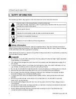
WARNING 


Do not hold the test leads or probes beyond the finger guards or tactile barriers 


Remove all probes, test leads and accessories that are not required for the test 


Always use proper terminals, switch position, and range for measurements 


Verify the instrument is operating correctly by measuring a known voltage before use. If in doubt, 
have the instrument serviced 


To avoid false readings that can lead to electric shock and injury, replace battery as soon as the 

low battery indicator “


BT


appears


Follow all legal requirements 


Obey posted instructions 


Never assume that a circuit is de-energized, check it first 


Always set up the measurement first, then connect the test leads and probes to the 
instrument before connecting to the circuit under test 


Connect the  ground  lead  first, then  the  voltage  leads  and the current  probe,  Disconnect  in 
the reverse order 


Route all test leads carefully 


Remove test leads from instrument before opening the battery door or instrument case 


CAUTION

:


The measurement inputs U1, U2 and U3 are not isolated from each other, input 

N is the common reference point. Connecting either U1, U2 or U3 to the circuit 
means that the others are also live and therefore a danger of electric shock is 
present. To avoid electrical shock, connect only the probes and test leads 
required for the test. 


Summary of Contents for IPM 3600N

Page 1: ...INSTRUCTION MANUAL IPM 3600N 3 Phase Power Analyser EN 3 4 1 2 MAG Q U12 Y M h NO P S U23 D h U31 m s...

Page 2: ......

Page 3: ...W Power System Measurement 18 5 3 Single Phase 3 Wire 1P3W Power System Measurement 20 5 4 Three Phase 3 Wire 3P3W2M Power System Measurement 22 5 5 Three Phase 3 Wire 3P3W3M Power System Measurement...

Page 4: ...emperature high humidity or condensation The instrument is designed for indoor use and can be safely used at temperatures ranging from 0 C to 40 C To prevent electric shock do not allow the instrument...

Page 5: ...Obey posted instructions Never assume that a circuit is de energized check it first Always set up the measurement first then connect the test leads and probes to the instrument before connecting to th...

Page 6: ...h and KVAh measurements Phase sequence indicator function Backlight display function Manual Data Memory and Read 50 sets Data logging micro SD CARD 4GB USB optical PC interface with three phase voltag...

Page 7: ...EC61010 2 032 Input AC 1000A maximum Output 0 35mV A Voltage test leads Category Rating CAT III 1000V AC 10A Max Alligator clip Category Rating CAT III 1000V AC 10A Max Category definitions Measuremen...

Page 8: ...B Maximum 99 blocks Current probe jaw opening diameter Cables 40mm Storage temperature and humidity 10 to 60 C R H 70 non condensing Dimensions Instrument 235x117x54 mm Current probe 193x88x40 mm Weig...

Page 9: ...lution Accuracy 0 1 to 999 9KVA 0 1KVA 1 0 rdg 20dgts 10 to 299 9A 1 5 rdg 20dgts 300 to 999 9A Measurement method Calculated from RMS voltage U and RMS current I Display item Apparent power of each c...

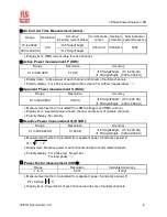
Page 10: ...1 U2 and U3 Active Power Energy measurement kWh Range Resolution Active power accuracy Timer interval Timer Accuracy 0 001 to 9 999KWh 0 001KWh 0 01 to 99 99KWh 0 01KWh 0 1 to 999 9KWh 0 1KWh 0 001 to...

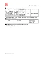
Page 11: ...0 1kVARh 0 001 to 9 999MVARh 0 001MVARh 0 01 to 30 59MVARh 0 01MVARh 1 0 rdg 20dgts 10 to 299 9A 1 5 rdg 20dgts 300 to 999 9A 1 sec 50ppm 25 C 77 F Measurement display Display all reactive power consu...

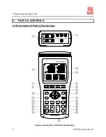
Page 12: ...e Power Analyser EN 9 09 30 16 Version No 00 IV PARTS CONTROLS 4 1 Description of Parts Control keys MAG Q U12 Y M h NO P S U23 D h U31 m s I3 I1 I4 I2 N U1 U2 U3 Figure 2 Description of Parts Control...

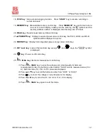
Page 13: ...easurement only 3P4W To measure three phase four wire power lines with neutral 7 key Phase sequence detection function key In the 3P4W mode press and hold down this key it will display phase detection...

Page 14: ...control key THDF Total Harmonic Distortion of a waveform is compared to its Fundamental THDR Total Harmonic Distortion of a waveform is compared to the waveforms rms value Press THD key to enter the V...

Page 15: ...d St123 symbols will be displayed in cycles 22 ENERGY key Display total integrated power energy value control key 23 KEY Lock key Lock all the functions key except and keys the LOCK symbol is displaye...

Page 16: ...V A kA W kW MW etc are automatically displayed to match the selected values and functions and mode of operation Q P 4 11 4 10 4 1 4 2 4 3 4 4 4 5 4 7 4 6 4 9 4 8 S 4 17 4 18 4 19 4 20 4 16 4 13 4 14 4...

Page 17: ...dicator and total reactive energy measured display indicator 4 10 DATA No Last manual datalogged memory address number indication 01 50 M Manual datalogged indication M displays one time store one set...

Page 18: ...hour display indicator 4 28 Display of Voltage or Date Day hour or THDR 4 29 Display of the rotary field direction 4 30 U3 indicates display of voltage on phase 3 THDR THDF or Harmonic 4 31 m s minute...

Page 19: ...y not protect you Adhere to local and national safety codes Personal protective equipment must be used to prevent shock and arc blast injury where hazardous live conductors are exposed Do not hold the...

Page 20: ...e the conductor inside the current probe jaw Make sure the probe is perpendicular to the conductor Ensure the arrow on the top of the probe faces towards the load of the circuit For optimal reading en...

Page 21: ...eutral G Ground Face the current probe arrows toward the load U2 N I3 I4 I1 I2 U1 U3 Figure 5 1P2W Wiring Connection Diagram Note U1 must be connected to the voltage source during the measurement of I...

Page 22: ...phase L1 To measure ground leakage current clamp the I4 current probe securely around the Ground Line G 5 Frequency Hz Phase Angle Ground Leakage Current I4 and Power Factor pF measurement Press PF ke...

Page 23: ...eutral G Ground Face the current probe arrows toward the load I3 I4 I1 I2 N U2 U1 U3 Figure 7 1P3W Wiring Connection Diagram Note U1 must be connected to the voltage source during the measurement of U...

Page 24: ...red voltage test alligator clip to Phase 1 L1 Connect the yellow voltage test alligator clip to Phase 2 L2 Clamp the I1 current probe securely around Phase 1 L1 11 Clamp the I2 current probe securely...

Page 25: ...yed and the final calculation time appears in the STOP line on the display Press key to exit the energy measurement mode and return to normal measurement mode 5 4 Three Phase 3 Wire 3P3W2M Power Syste...

Page 26: ...Connect the I1 current probe to the I1 socket Connect the I2 current probe to the I2 socket 4 Connect the voltage test leads and current probes to the electrical equipment to be tested as shown in Fig...

Page 27: ...Please refer to section 4 1 25 MAG key description 9 Power Maximum Minimum measurement Please refer to section 4 1 10 MAX key description 10 Energy measurement Press ENERGY key the Pt Qt St and PFt o...

Page 28: ...3W3M Power System Measurement Using 3 power meter method L1 L2 L3 Phase 1 Phase 2 Phase 3 G Ground Face the current probe arrows toward the load I4 I3 I1 I2 N U1 U2 U3 Figure 11 3P3W3M Wiring Connecti...

Page 29: ...around Phase 1 L1 11 Clamp the I2 current probe securely around Phase 2 L2 12 Clamp the I2 current probe securely around Phase 3 L3 5 Press POWER key to select between Phase 1 P1 Q1 S1 PF1 Phase 2 P2...

Page 30: ...Three Phase 4 Wire 3P4W Power System Measurement L1 L2 L3 Phase 1 Phase 2 Phase 3 N Neutral G Ground Face the current probe arrows toward the load I4 I3 I1 I2 N U1 U2 U3 Figure 13 3P4W Wiring Connecti...

Page 31: ...t probes Connect the black voltage test alligator clip to the neutral conductor N Connect the red voltage test alligator clip to Phase 1 L1 11 Connect the yellow voltage test alligator clip to Phase 2...

Page 32: ...played and the final calculation time appears in the STOP line on the display Press key to exit the energy measurement mode and return to normal measurement mode 5 7 Single Phase Current Measurement L...

Page 33: ...9 Auto Data logging Function Operation 1 Clear SD Card memory data Press key to turn off the meter Press and hold down the MEMORY key then press key again to turn on the meter and to enter clear manu...

Page 34: ...9 When the maximum block or maximum capacity is full the DATA FULL symbol will be displayed and data recording is automatically stopped 4 Download data to PC Please refer to the software manual CD ROM...

Page 35: ...4 3P4W Phase Sequence Connection Diagram CAUTION Where possible isolate the power to the electrical circuit to be tested before connecting the voltage test leads and current probes Connect the red vol...

Page 36: ...sleep mode after approximately 30 minutes to save power consumption when enable auto power function 1 Enable auto power off procedure Press key to turn off the instrument Press and hold down the TIME...

Page 37: ...batteries of different types or old and new batteries Check the battery polarity carefully when inserting the batteries Do not short circuit used batteries disassemble them or throw them in a fire do...

Page 38: ...35 09 30 16 Version No 00 VII SOFTWARE INSTALLATION AND OPERATION For the detailed instructions please refer to the content of the CD ROM which has the complete instructions for the software operation...

Page 39: ...eration contamination or abnormal conditions of operation or handling Any implied warranties arising out of the sale of this product including but not limited to implied warranties of merchantability...

Page 40: ...d Shanghai 200001 China www rs components com Europe RS Components Ltd PO Box 99 Corby Northants NN17 9RS United Kingdom www rs components com Japan RS Components Ltd West Tower 12th Floor Yokohama Bu...

Reviews: