background image

PARTS & CONTROLS / EN

04/26/13 Version No. 01

EN-5

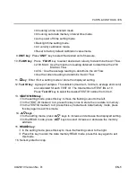
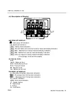
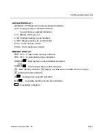
 Choosing a time constant mode.

 Choosing auto data memory interval time mode.

 Auto power off time setting mode.

 Backlight time setting mode.

 Air velocity calibration mode.

 Reset to factory default calibration value mode.

9. UNIT key : Press “UNIT” key to select the desired unit of measure.

10. FLOW key : Press “FLOW” key to select desired air velocity to determine the Air Flow.

 2/3V MAX : Use the maximum reading obtained to determine the 2/3V

MAX Air Flow.

 AVG : Use the average reading to determine the Air Flow.

 Use the current reading to determine the Air Flow.

11. 

↵↵

 key : Enter / Exit a setting mode or store the displayed setting.

12. Test ID key : A group of samples.  The statistics (maximum, minimum, average and count)

are calculated for each TEST ID.  The total number of TEST IDs is 10.
Press “Test ID” key to select the desired TEST ID number from 0 to 9.

13. 

AUTO MEM key :

 In the setting mode, press this key to move the flashing cursor to the left.

 In the TEST ID modes 0 to 4, press this key once to store the one data to memory.

 In the TEST ID modes 5 to 9, press this key to start auto data memory mode, press

this key again to exit this mode.

14. 

 keys :

 In the setting mode, press “

 keys to increase or decrease the displayed setting.

 In the READ mode, press “

 keys to select increase or decrease the memory

address.

15. READ

 key :

 In the setting mode, press this key to move the flashing cursor to the right.

 Press this key to enter the data memory READ mode, press this key again to exit

this mode.

16. Sensor protection cap.

Summary of Contents for RS-1340

Page 1: ...RS Stock No 724 4207 Instruction Manual RS 1340 Hot Wire Anemometer FR EN IT DE ES...

Page 2: ...ASURING PROCEDURE 8 5 1 Getting Started 8 5 2 Settings and Calibrations 8 5 3 Air Velocity Measurement 10 5 4 Air Flow Measurement 10 5 5 MAX MIN AVG Recording Measurement 11 5 6 Air Velocity Manual D...

Page 3: ...flow make certain that you can safely raise and hold the meter while making measurements Be especially careful when working on a ladder Observe all necessary precautions so that the unit does not bec...

Page 4: ...and mass flow measurement in ducts Applications HVAC system performance Commissioning Plant maintenance Critical environment certification Duct traverses FEATURES Fast response probe Air flow volume...

Page 5: ...Data Memory Capacity 5 x 99 sets Auto Data Memory Capacity 5 x 99 sets Operation Temperature Range Meter 0 to 50 C 32 to 122 F Probe 10 to 60 C 14 to 140 F Storage 20 to 60 C 4 to 140 F Operation Con...

Page 6: ...ss power key to turn the meter on or off 5 H HOLD key Press H Hold key to freeze or unfreeze the display reading In H mode press UNIT key to select the desired unit of display 6 key Press key to turn...

Page 7: ...t ID key A group of samples The statistics maximum minimum average and count are calculated for each TEST ID The total number of TEST IDs is 10 Press Test ID key to select the desired TEST ID number f...

Page 8: ...isplay indication REC MIN Minimum air velocity measured display indication REC AVG Average air velocity measured display indication The average of the last 30 samples Air Velocity Units knots mile hr...

Page 9: ...by one thousand ft3 min Cubic feet per minute m3 min Cubic metres per minute MEMORY DISPLAY TEST ID 0 4 Manu data memory indication TEST ID 5 9 Auto data memory indication SAMPLE Data memory number ad...

Page 10: ...le tube make sure the sensor window is fully exposed and is facing upstream If in the right direction the user will see the red ink marking as following figure 4 Retracting the Probe To retract the pr...

Page 11: ...to exit the setting mode 2 Choosing a Time Constant mode Press SET key twice to enter this mode the TC symbol and the current time constant are displayed Press and keys to scroll through the choices a...

Page 12: ...d enter the air velocity scale factor calibration mode the scale factor value is displayed Insert the meter probe into the calibration tunnel with the sensor window toward the air flow Secure the prob...

Page 13: ...y through the maximum REC MAX minimum REC MIN average REC AVG and current REC air velocity readings 3 Press H HOLD key to pause recording the H symbol is displayed press H HOLD key again to resume rec...

Page 14: ...ory size is 99 sets per each IDs Press AUTO MEM key again to exit this mode If the flow parameters are change when in the read mode the TEST ID will automatically increment 3 Press READ key to enter R...

Page 15: ...ondition of the battery should be checked prior to use and changed if necessary The LCD display will show symbol when the battery power is not sufficient for accurate testing 1 Remove discharged batte...

Reviews: