4
5
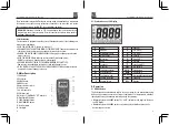
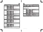
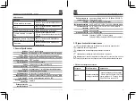
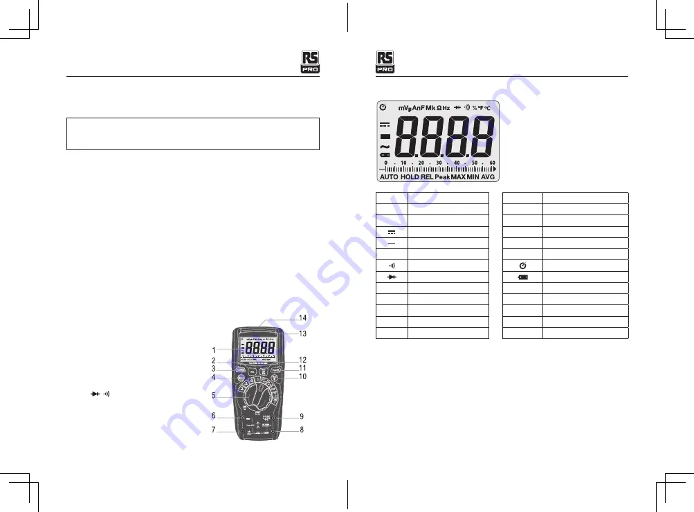
4-1. Symbols Used on LCD Display
V
Volts
A
Amperes
~
Alternating current
Direct current
Minus sign
Ω
Ohms
Continuity
Diode test
F
Farads(capacitance)
Hz
Hertz(frequency)
%
Percent(duty ratio)
o
F
Degrees Fahrenheit
o
C
Degrees Celcius
n
nano(10 )
μ
-6 micro(10 )
m
-3 milli(10 )
k
3 kilo(10 )
M
6 mega(10 )
OL
Overload
Auto Power Off
Low battery
AUTO
Autoranging
HOLD
Display hold
MAX/MIN/AVG
Maximum/Minimum/Average
Peak
Peak hold
REL
Relative
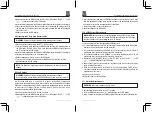
5. Operation
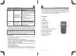
5.1 RANGE Button
The Autorange mode automatically selects the proper range for the measurement being
made and is generally the best mode for most applications. For measurement situations
requiring that a range be manually selected, perform the following:
• Momentarily press the RANGE button. The “AUTO” indicator will no longer be shown on
the LCD display.
• Momentarily press the RANGE button to step through the available ranges until the
desired range is selected.
True RMS Digital Multimeter/ English
13/12/2017 Version No. 001
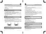
The measurement category(CAT)rating and voltage rating is determined by a combination
of the meter, test probes and any accessories connected to the meter and test probes.
The combination rating is the LOWEST of any individual component.
WARNING:
Operation is limited to CAT II applications when the insulated tips are
removed from one or both test probes. Refer to Input Limits section in this manual for
maximum voltage ratings.
3-3.Maintenance
This multimeter is designed to provide years of dependable service, if the following care
instructions are performed:
• KEEP THE METER DRY. If it gets wet, wipe it off.
• USE AND STORE THE METER IN NORMAL TEMPERATURES. Temperature extremes can
shorten the life of the electronic parts and distort or melt plastic parts.
• HANDLE THE METER GENTLY AND CAREFULLY. Dropping it can damage the electronic
parts or the case.
• KEEP THE METER CLEAN. Wipe the case occasionally with a damp cloth.
DO NOT use chemicals, cleaning solvents, or detergents.
• USE ONLY FRESH BATTERIES OF THE RECOMMENDED SIZE AND TYPE.
Remove old or weak batteries so they do not leak and damage the unit.
• IF THE METER IS TO BE STORED FOR A LONG PERIOD OF TIME, the batteries should
be removed to prevent damage to the unit.
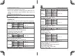
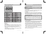
4. Meter Description
1. LCD display
2. REL button
3. RANGE button
4. MODE button
5. Rotary function switch
6. 10A input jack
7. μA, mA input jack
8. COM input jack
9.
V
/
Ω
/ / /
CAP
/
Hz%
/
o
C
o
F
input jack
10. Backlight/HOLD button
11. PEAK/Flashlight button
12. MAX/MIN/AVG button
13. Auto backlight
14. Flashlight
True RMS Digital Multimeter/ English
13/12/2017 Version No. 001
Summary of Contents for RS-965T
Page 44: ...17...


