3
Note: These die sets are to be used in conjunction with tool frame RS
stock no. 849-114 and for crimping the above contacts:
Installation and removal of die set and locator
assembly (figure 1)
1. Open the tool handles and remove the two die retaining screws
from the tool jaws.
2. Place the wire anvil and insulation anvil so that their chamfered
sides and their marked surfaces face outward, when mounted in the
lower jaw of the tool frame.
3. Insert the two die retaining pins.
4. Insert the short die retaining screw through the jaw and both anvil
dies, and tighten the screw just enough to hold the dies in place.
Do not tighten the screw completely at this time.
5. Place the wire crimper and insulation crimper so that their
chamfered sides and their marked surfaces face outward, when
mounted in the upper jaw of the tool frame.
6. Insert the two die retaining pins.
7. Insert the long die retaining screw through the jaw and both crimper
dies, and tighten the screw just enough to hold the dies in place. Do
not tighten the screw completely at this time.
8. Carefully close the tool handles, making sure that the anvils and
crimpers align properly. Continue closing the tool handles until the
ratchet in the tool frame has engaged sufficiently to hold the anvils
and crimpers in place, then tighten both die retaining screws.
9. Place the locator assembly over the end of the long screw, and
position the locator assembly against the side of the tool jaw.
10. Place the nut onto the end of the long screw and tighten the nut
enough to hold the locator assembly in place, while still allowing the
locator to slide up and down.
11. To disassemble, close the tool handles until the ratchet releases,
remove the nut, the locator assembly, the two die retaining screws,
and the four die retaining pins, and slide the anvils and crimpers out
of the tool jaws.
Contact support adjustment (figure 2)
Note: The contact support is preset prior to shipment, but minor
adjustment may be necessary.
1. Make a simple crimp and determine if the contact is straight,
bending upward, or bending downward.
2. If adjustment is required, loosen the screw that holds the contact
support onto the locator assembly.
Note: The ratchet has detents that create audible clicks as the tool
handles close.
3. Place a contact with wire into the proper nest and close the tool
handles until the ratchet reaches the sixth click, or until the contact
support touches the contact.
4. Slightly loosen the nut that holds the locator assembly onto the tool
frame.
5. Move the contact support as required to eliminate the bending of the
contact.
6. Tighten the nut and close the handles until the ratchet releases.
7. Remove and inspect the contact.
8. Make another sample crimp. If the contact is straight, tighten the
contact support screw. If the contact is still being bent during
crimping, repeat the adjustment procedure.
Crimping procedure (figures 2 and 3)
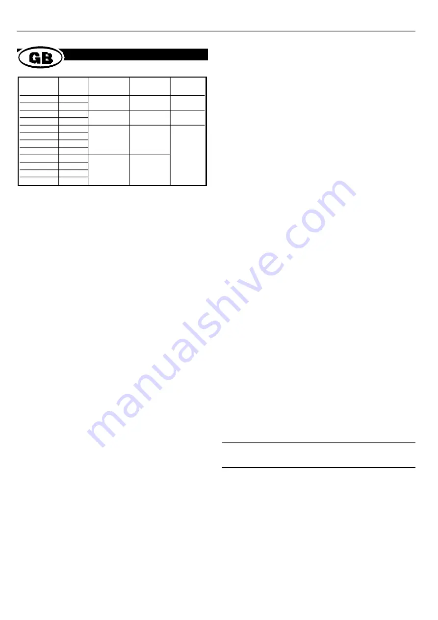
With the correct contact and wire size as defined in the table above,
strip the wire back to give 4mm of conductor. Proceed as follows.
1. Hold the tool so that the back (wire side) is facing you. Squeeze tool
handles together and allow them to open fully.
2. Holding the contact by the mating end, insert the contact - insulation
barrel first - into the appropriate crimp section.
3. Position the contact so that the mating end of the contact is on the
locator side of the tool, and so that the open "U" of the wire and
insulation barrels face the top of the tool. Place the contact up into
the nest so that the movable locator drops into the slot in the
contact. Refer to figure 3. Butt the front end of the wire barrel
against the movable locator.
CAUTION: Make sure that both sides of the insulation barrel are
started evenly into the crimping section. Do not attempt
to crimp an improperly positioned contact.
4. Hold the contact in position and squeeze the tool handles together
until the ratchet engages sufficiently to hold the contact in position.
Do not deform insulation barrel or wire barrel.
5. Insert stripped wire into contact insulation and wire barrels until it is
butted against the wire stop, as shown in figure 3.
6. Holding the wire in place, squeeze tool handles together until
ratchet releases. Allow tool handles to open and remove crimped
contact.
Note:
The crimped contact may stick in the crimping area, but
the contact can be easily removed by pushing downward
on the locator (see figure 3).
RS Components shall not be liable for any liability or loss of any nature (howsoever
caused and whether or not due to RS Components’ negligence) which may result
from the use of any information provided in RS technical literature.
Wire size
RS
stock no. Contact
Conductor
Insulation
Die Set
849-079
pin
24-18 a.w.g.
1-2.5mm
849-136
849-091
socket
849-085
pin
20-14 a.w.g.
1.5-3.3mm
849-120
849-108
socket
372-377
pin
372-406
socket
24-20 a.w.g.
1.02-2.03mm
372-850
pin
372-412
socket
372-440
372-383
pin
372-428
socket
18.16 a.w.g. 2.03-2.54mm
372-399
pin
372-434
socket
.
V9720


