FOCUS 320 SBR Owner's Manual
16
RSF Woodburning Fireplaces
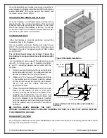
Once the standoffs are in place, make sure to seal the ¼"
gap between the fireplace and the standoffs with silicone
sealant.
DO NOT
fill the gap behind the sealant with
insulation or any other material.
SECURING THE FIREPLACE IN PLACE
Once the fireplace is in its final location, take the time to
attach it to the floor. Using at least two of the five small
brackets that were securing the fireplace to the crate,
attach the casing of the fireplace to the floor. If possible,
try to have at least one, if not two, of the brackets screwed
into the floor joists with 2" wood screws.
OUTSIDE AIR DUCT
After the fireplace is correctly positioned, connect the
outside air inlet to the fireplace.
Use an insulated aluminium flexible duct rated at over
200° F. The duct should not exceed 12' vertical rise above
the base of the unit. We suggest using the 4" RSF outside
air kit (FO-INT).
The air inlet should always be at least 5’ lower than
the chimney rain cap and must never terminate in attic
spaces.
A 4" diameter duct can be used if the total duct run is less
than 25'. For longer runs, use 5" diameter duct. Both
4" and 5" connecting sleeves are provided with the
fireplace.
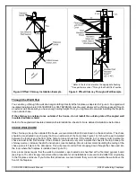
1. Find a convenient location for the insulated flexible
duct and outside air inlet. The outside air inlet can
be above or below floor level (see Figure 6).
2. Make a 4 ¼" (5 ¼" if using a 5" diameter duct) hole
in the outside wall of the house. Push the outside
air inlet in from the outside. Seal the joint between
the air inlet and the outside wall with an
appropriate sealant.
3. Place the insulated flexible duct over the round
sleeve on the outside air inlet. At both ends,
carefully pull back the insulation and plastic cover,
exposing the flexible duct. Then at each end,
attach the duct with metal screws to the air inlet
and to the fireplace connecting sleeve. Carefully
push the insulation and cover back over the duct.
Tape the plastic cover in place with 2" aluminium
duct tape.
❖
CAUTION: WHEN RUNNING THE DUCT
AROUND CORNERS, BE SURE TO PREVENT CRIMPING THE DUCT IN A WAY THAT WOULD RESTRICT
THE COMBUSTION AIRFLOW.
MANDATORY OPTIONS
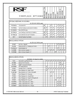
Do not forget to install the louvers (FO-F320SBRLB) or the Clean Face Option (FO-F2) along with the two required
Gravity Vent Kits (FO-V2 or FO-V3).
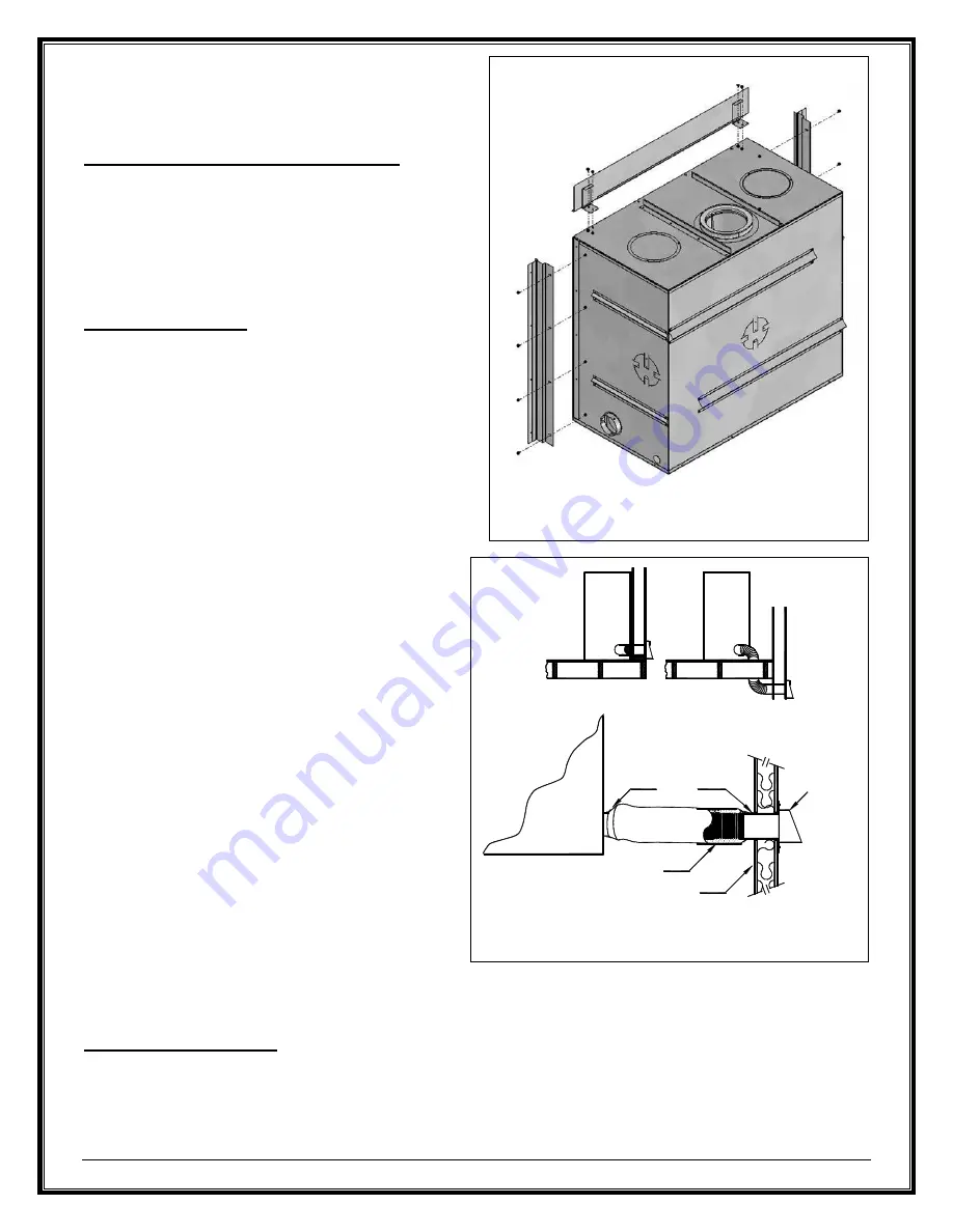
Figure 5 Standoffs Installation
Figure 6 Outside Air Connection and Installation
Example
Above Floor
Example
Below Floor
Example
RS
F
Fi
re
pl
ac
e
RS
F
Fi
re
pl
ac
e
RS
F
Fi
re
pl
ac
e
2" Aluminium
Duct Tape
Insulated Flexible Air Duct
Outside Wall
Outside Air
Inlet

