background image

PEARL 3600 Owner's Manual 

11 

RSF Woodburning Fireplaces 

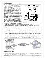
8.  Orient the outside air elbow in the direction you want the outside air duct to go and tighten the screws.  

9.  Make a 4 ¼" (5 ¼" if using a 5" diameter duct) hole in the outside wall of the house. Push the outside air inlet 

in from the outside. Seal the joint between the air inlet and the outside wall with an appropriate sealant. 

10. Place the insulated flexible duct over the round sleeve on the outside air inlet. Carefully pull back the insulation 

and plastic cover, exposing the flexible duct. Attach the duct with metal screws to the air inlet. Replace the 

insulation and cover back over the duct. Tape the plastic cover in place with aluminium duct tape. 

 CAUTION: WHEN RUNNING THE DUCT AROUND CORNERS, BE SURE TO PREVENT CRIMPING THE 

DUCT IN A WAY THAT WOULD RESTRICT THE COMBUSTION AIRFLOW. 

FINISHING AROUND THE FIREPLACE  

The decorative faceplate of the PEARL3600 fireplace is not meant to be covered, it is meant to be admired. 

DO 

NOT

 cover the decorative faceplate of the fireplace or any of its louvers. 

The decorative faceplate of the PEARL3600 extends ½" beyond the sides of the fireplace to be able to hide the 

edge of the finishing material behind it. The decorative faceplate sits 1" proud of the top of the fireplace casing to 

allow thin finishing materials to slip behind the rounded top of the decorative faceplate.  
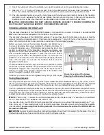
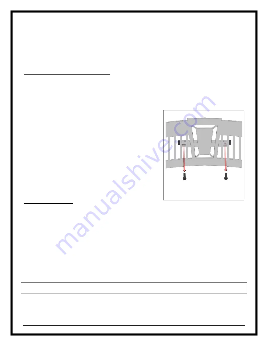
Before you begin, remove the decorative faceplate and bottom louver 

to prevent damaging them while installing the finishing materials. To 

remove the faceplate, use a 5/32 Allen key and remove the two screws 

located on either side of the faceplate’s keystone centerpiece  (see 

Figure 8) Once the bolts are removed, the faceplate will be loose, so 

with one hand holding the faceplate in place, close the door. Take a 

good grip on both side  of the faceplate and lift it up. There are two 

brackets, one on each lower side, that need to be disengaged from the 

base of the fireplace. Do not lose the hardware  that secures the 

faceplate to the fireplace. 
To remove the bottom louver, simply open the door, grab the top of the 

louver close to each extremity and pull forward. There are two high 

temperature magnets, one on each side, close to the top of the louver 

keeping it in place along with two supports close to the bottom of the 

louver to support the weight of the louver. 
If desired, you can also remove the glass door by lifting it off its hinges 

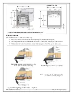
Facing Requirements 

Finishing materials that cover the facing of the fireplace MUST BE NON-COMBUSTIBLE (e.g. brick, slate, ceramic 

tile, etc.). Drywall cannot get closer to the fireplace than the side and top standoffs. The front face of the top standoff 

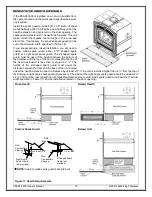
is considered part of the fireplace facing. The minimum size of a non-combustible facing is shown in Figure 9. 
The non-combustible finishing materials may be installed so that they fit behind the decorative faceplate. Plan the 

finishing of the fireplace in advance and plan for the material thickness including the adhesive coat. If you are using 

a thin material (such as tile) and plan to install your finishing behind the decorative faceplate, you MUST be able to 

reinstall the decorative facing properly or it may become a safety hazard. 

 NOTE: 

There is only 1” between the decorative faceplate and the fireplace body. For example, this is sufficient 

for a ½” cement board, a 

⅛”

 adhesive coat, and a 

” tile. 


You can also finish your PEARL3600 with materials that will result in a combined thickness greater than 1" (e.g. 

brick, stone, etc.). These materials will not fit behind the decorative faceplate and will protrude past the faceplate 

once installed. 

If you are using thick finishing materials, then the decorative faceplate of the PEARL3600 can 

be used as a template.


 WARNING 

Gypsum boards or any other combustible material cannot touch the casing of the fireplace. Only non-

combustible material such as cement board can touch the fireplace casing. 


Figure 8 Location of the Screws 

Securing the Decorative Faceplate 

Summary of Contents for PEARL 3600

Page 1: ...l Residential Factory Built Fireplace Operation Maintenance Installation PEARL 3600 Keep these instructions for future use Industrial Chimney Company Inc 400 J F Kennedy St Jerome QC Canada J7Y 4B7 Telephone 450 565 6336 www icc rsf com ...

Page 2: ... CONTENT SAFETY FIRST 3 DO S AND DONT S 3 CREOSOTE FORMATION AND REMOVAL 3 GENERAL SPECIFICATIONS 4 OPTIONS 4 UNIT DIMENSIONS AND CLEARANCES 5 INSTALLATION 7 GENERAL INSTALLATION 7 LOCATION 8 FRAMING 8 CEILING CLEARANCE 9 SECURING THE FIREPLACE IN PLACE 9 TOP STANDOFF INSTALLATION 9 OUTSIDE AIR DUCT 10 FINISHING AROUND THE FIREPLACE 11 CHIMNEY 14 CHIMNEY INSTALLATION 14 OFFSET CHIMNEY 15 CHASE ENC...

Page 3: ...ate of the fire or if the chimney connector behind the top louver glows red you are overfiring the fireplace 10 DO NOT use a fireplace grate or other products not specified for use with this fireplace 11 The burn rates are set by the manual air control at the factory DO NOT tamper with the air control DO NOT install a flue damper that would allow you to reduce the chimney draft and thus slow the m...

Page 4: ...ity vent kit includes 5 of insulated flexible ducting a gravity vent starter an outlet grill adapter and a decorative outlet grill The different grill designs are shown below FO V2 FO VGC grill only for FO V2 FO V3 Heat Dump FO HD For a simple way to pull heat away from the fireplace to another room or to the basement we offer the Heat Dump Kit It includes a 180 cfm blower and is most often used t...

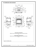
Page 5: ...UNIT DIMENSIONS AND CLEARANCES For the side wall clearance Distance from the side standoff to the side of the firebox opening 81 8 For the mantel shelf clearance Distance from the fireplace base to the top of the firebox opening 25 Figure 1 Unit Dimensions ...

Page 6: ...le 4 if elbows are present 12 3 66 m E Maximum chimney height maximum total chimney height from fireplace top to below the chimney rain cap 36 13 72 m F Maximum chimney height supported by the fireplace 20 6 10 m G Minimum depth of non combustible hearth extension from the front of the fireplace 18 457 mm H Minimum width of non combustible hearth extension total width must be centered on the fireb...

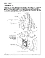
Page 7: ...nstallation requirements and the need to obtain a permit NOTE We recommend that you remove the door until after all finishing work is completed around the fireplace This will reduce the possibility of scratches vandalism or damage to the finish caused by drywall dust muriatic acid plaster cement paint or any other harmful spray or liquid Figure 3 PEARL3600 General Installation Flashing and Roof Ra...

Page 8: ... 2 Do not build recessed shelves or cupboards in the enclosure above the fireplace This must be kept as air space 3 If at all possible run the chimney up through the inside of the house If it must be run outside it should be enclosed in an insulated enclosure see Installation Chase Enclosure Remember a cold chimney causes poor draft FRAMING Walls on all interior sides of the fireplace enclosure sh...

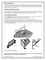
Page 9: ...two of the brackets screwed into the floor joists with 2 wood screws TOP STANDOFF INSTALLATION The Top Standoff provides clearance to combustible framing and includes a heat shield as part of its design The Top Standoff MUST be installed to avoid fire and ensure a safe installation Screw the Top Standoff to the top of the unit in the location shown using the screws provided For shipping the top st...

Page 10: ...d flexible duct has a plastic covering remove this plastic cover over the flexible duct so that there is no plastic cover on the duct under the fireplace and for at least 3 away from the fireplace The plastic cover MUST NOT get within 3 of the fireplace 5 Tape the insulation to the aluminum ducting where the plastic cover was pulled back Using aluminium tape to hold it in place 6 If using 5 flexib...

Page 11: ...r side that need to be disengaged from the base of the fireplace Do not lose the hardware that secures the faceplate to the fireplace To remove the bottom louver simply open the door grab the top of the louver close to each extremity and pull forward There are two high temperature magnets one on each side close to the top of the louver keeping it in place along with two supports close to the botto...

Page 12: ...e a flat facing look 2 Thin facing materials such as ceramic tiles that are less than 1 thick including the adhesive coat 3 Thicker materials that will result in a combined thickness greater than 1 e g brick stone etc Flat Facing requires cement board due to the direct contact to the fireplace casing Thin Facing 1 including the drywall Thick Facing 1 Note Framing shown is based on the recommended ...

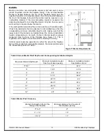
Page 13: ...ght while making sure that the lowest point of the mantel is not installed lower the minimum installation height corresponding to its depth Table 2 Mantel depth is always measured from the face of the fireplace see Figure 11 This is regardless of the depth of materials used for finishing the facing Vertical mantel posts are permitted on either the side of the fireplace facing If they made from com...

Page 14: ...6 17 18 6 20 24 21 26 6 9001 10000 16 6 17 6 19 20 6 24 6 22 27 Flue height is measured from the top of the fireplace to the top of the chimney before installing the rain cap If you have two different offsets two pairs of different elbows simply use the column for two offsets of the biggest pair of elbows at your elevation to get your Minimum Flue Height CHIMNEY INSTALLATION Make sure to read the ...

Page 15: ...aximum offset angle In USA 30 In Canada 45 Maximum number of elbows four resulting in two offsets and returns Install the fireplace and chimney as described earlier When you require an elbow proceed as follows 1 Install the required elbow Turn it in the desired direction and fasten it to the chimney length with the three metal screws provided at the joints 2 Install enough lengths to obtain the de...

Page 16: ...ible exterior wall e g concrete the angled wall radiation shield is not required An opening slightly larger than the chimney can be created through the non combustible wall Any gaps between the chimney and wall can be filled with rock wool insulation and then sealed with silicone Refer to text to determine the appropriate flashing Figure 13 Offset Chimney Installation Example Figure 14 Offset Chim...

Page 17: ...t to a listed liner that will run up inside the masonry chimney see Figure 16 The stainless steel liner should be fitted inside the clay liner all the way to the top of the masonry chimney It is not meant to replace the clay liner You can use either the EXCEL liner or any other listed liner to ULC S635 ULC S640 or UL 1777 Special care is to be taken to make sure that you have a good solid connecti...

Page 18: ...e to the size required Remember to work from the center out Be especially careful with the clay liner behind the brick because three sides of it must stay in place 3 Bring the stainless steel liner down from the top of the chimney If you are using a rigid liner you will need enough room to secure an elbow to it with at least two screws If it is difficult to install rigid stainless steel liner in t...

Page 19: ...be used if the height between the bottom of the fireplace and the top of the non combustible flooring of the hearth extension is less than or equal to 2 The height of the Z shaped spark guard must equal the distance between the floor and the base of the unit and go under the hearth extension and the fireplace by at least 2 If the unit is installed higher than 2 from the top of the flooring a right...

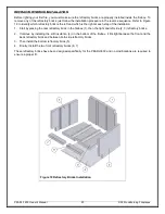
Page 20: ...at each step of the installation 1 Start by placing the rear refractory brick in the firebox 1 then the right and left side 2 3 refractory bricks 2 Continue by installing the soft insulation 4 on the bottom of the firebox It fits tight between the front and the back refractory brick and between both side refractory bricks 3 Then install the bottom refractory brick 5 4 Finally install the two front...

Page 21: ...t a little longer before attempting to restrict the air again If there s no change to the burn pattern you can continue to close the combustion air further Always close the combustion air control gradually never from maximum to minimum in an instant Eventually you should be able to close the combustion air all or most of the way There should always be visible fire inside the firebox at every step ...

Page 22: ... your kindling about 20 pieces the size of your fingers on top of the small wood You can then add a few pieces of paper on top Never use any flammable liquid Light the fire at the top of the pile and close the door most of the way but do not shut it completely If the door is positioned correctly you will see air rushing into the fireplace this will help the lighting process Wait about 2 minutes an...

Page 23: ...ure While there is still moisture in the bricks they will be black with smoke deposits When the moisture has dissipated the bricks will turn white Unlike cast iron stoves there is no need to cure the fireplace itself by starting with small fires and progressively larger ones Feel free to light a large fire from the very start You will experience a slight odor during the first few fires This odor c...

Page 24: ... more hot air flow up the chimney which means you are sacrificing efficiency Fast burning fires lots of air go through much more wood than slow burning fires To get the most out of your PEARL3600 fireplace adjust the combustion air control lever at the appropriate time If the fire seems to be burning too quickly turn the air down If the fire is smoldering and there are no visible flames turn the a...

Page 25: ... to secure it DISPOSAL OF ASHES Remove the ashes before they become too deep i e before you have a spillage problem when you open the door The ashes should be placed in a metal container with a tight fitting lid The closed container of ashes should be placed on a non combustible floor or on the ground well away from all combustible materials pending final disposal If the ashes are disposed of by b...

Page 26: ...ion in the room from the time you start painting until the paint is dry Stove Bright is available in a wide range of colors if you want to change the color of your PEARL3600 We recommend that you take the time to protect or remove any item that you do not want to paint such as the door glass the fireplace surroundings etc DOOR ADJUSTMENT To check for a proper door seal insert a sheet of paper betw...

Page 27: ...PEARL 3600 Owner s Manual 27 RSF Woodburning Fireplaces LISTING LABEL The listing label is glued to the bottom of the fireplace Just remove the bottom louver the listing label is below the floor shield ...

Page 28: ...PEARL 3600 Owner s Manual 28 RSF Woodburning Fireplaces COMPLETE OPTIONS LIST ...

Page 29: ...PEARL 3600 Owner s Manual 29 RSF Woodburning Fireplaces ...

Page 30: ...er s Manual 30 RSF Woodburning Fireplaces REPLACEMENT PARTS Use only genuine RSF parts The use of any substitutes will void the warranty and may put your safety at risk Will be available soon Contact your RSF dealer ...

Page 31: ...ractory components or baffle Repairs or replacements necessitated by vandalism neglect abuse over firing improper fuel or fuel loads or failure to adequately service the unit as stated in the owner s manual Repairs or replacements particularly charges for travel and labor not authorized by RSF Woodburning Fireplaces in advance LIMITATIONS All items found to be defective will be replaced or repaire...

Reviews: